00194340-01.pdf - 第14页
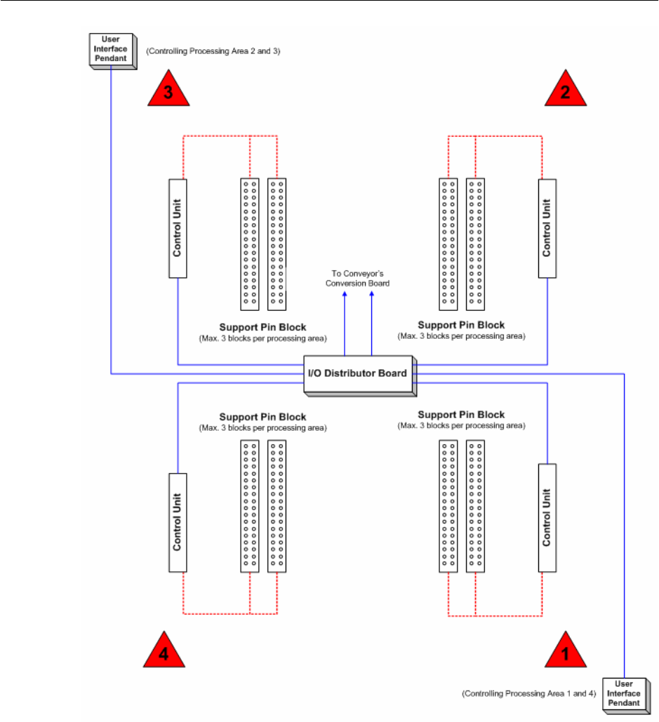
Retrofit Instructions & User’s Manual / Automatic Vacuum Support Pins (AVSP) Edition 04/2006 Figure 1.3.1-5 Overview of interconnection on dua l conveyor SIPLACE machine (HF & HS-60) 1-10
Retrofit Instructions & User’s Manual / Automatic Vacuum Support Pins (AVSP)
Edition 04/2006
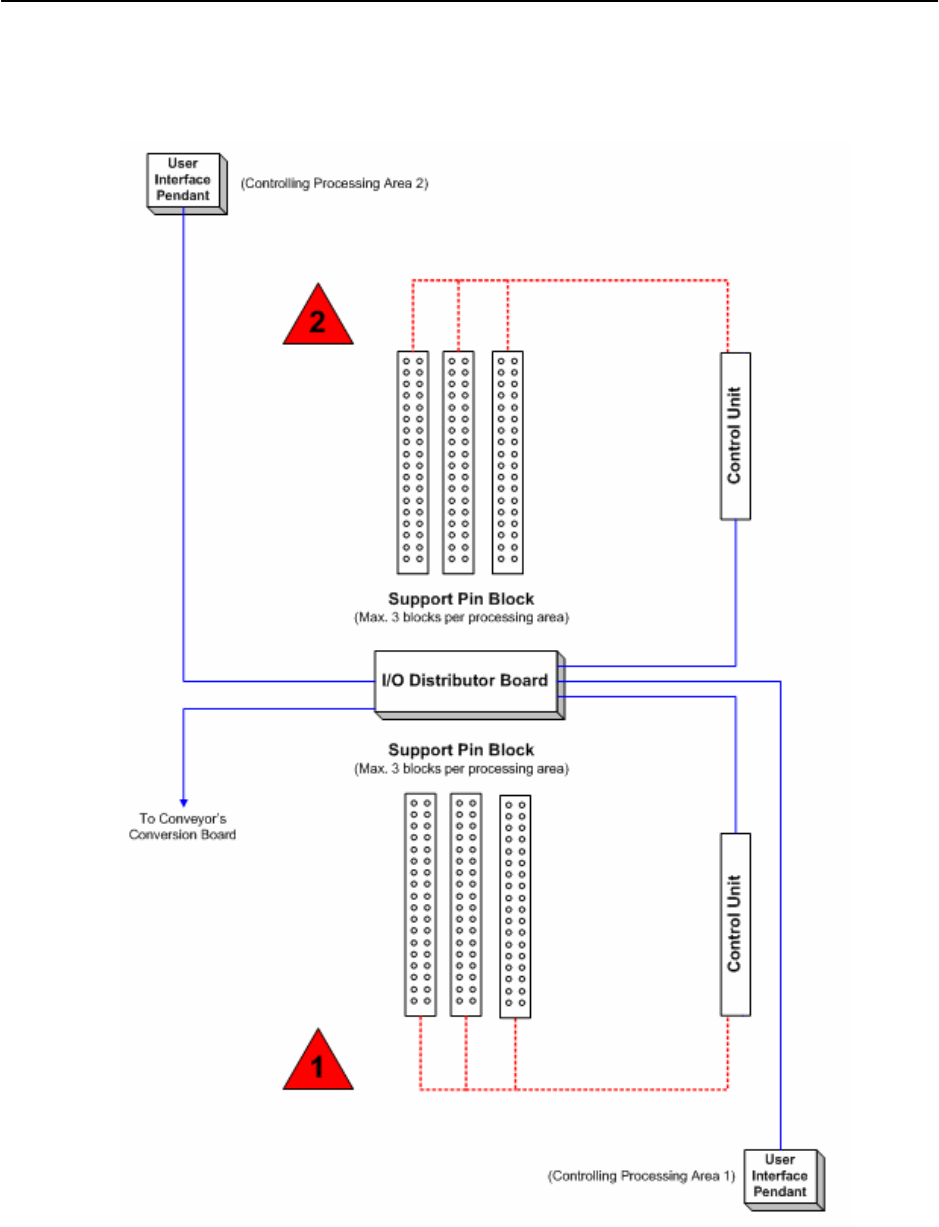
These components are connected to each other electrically and pneumatically to function.
Figures below show an overview of interconnection on both the single and dual conveyor
SIPLACE HS-60 machine.
Figure 1.3.1-4 Overview of interconnection on single conveyor SIPLACE machine (HF & HS-60)
1-9
Retrofit Instructions & User’s Manual / Automatic Vacuum Support Pins (AVSP)
Edition 04/2006
Figure 1.3.1-5 Overview of interconnection on dual conveyor SIPLACE machine (HF & HS-60)
1-10

Retrofit Instructions & User’s Manual / Automatic Vacuum Support Pins (AVSP)
Edition 04/2006
1.3.2 Product specifications
Pin module dimension (LxWxH) 395mm x 40mm x 100mm
Rubber end cap diameter 6mm (Standard)
(Material: NBR 60° Shore A, 10
Ω /sq)
11
Rubber vacuum cup diameter 9mm (Standard)
(Material: Conductive Silicone)
Max. support force per pin 30N
Contact force during teaching Less than 1.5N (150gm)
Max. component height 15mm
Re-teaching time Less than 2 minutes
Changeover time from AVSP option
to standard magnetic support pin
Less than 10 minutes
Compressed air supply 5.5 bar min., 250Nl/min, 5 μm air filter & oil separator
Max. air consumption 200 Nl/min. (when vacuum is turn ON on 4
placement areas)
Station software version 503.04
Table 1.3.2-1 Product Specifications
1-11