00194340-01.pdf - 第19页
Retrofit Instructions & User’s Manual / Automatic Vacuum Support Pins (AVSP) Edition 04/2006 → Open the cover of pneumatic compartm ent from the machine. Locate the air service unit 03039864-FS to frame of the machin…
Retrofit Instructions & User’s Manual / Automatic Vacuum Support Pins (AVSP)
Edition 04/2006
2.4 Mechanical and electrical installation
WARNING
Before start installing or uninstalling any air supply, make sure the main valve for
compressed air input to machine is shut off.
WARNING
Before start installing or uninstalling any electrical components, make sure the main power to
machine is shut off and machine is disconnected from the mains.
2.4.1 Compressed air supply installation
→ Remove all feeder tables from the machine and subsequently remove all top plate of
lifting table by removing 4 countersunk screws on each of the table. This will allow more
space during installation.
NOTE
Standard lifting table top plate is not usable with AVSP. AVSP option plate is required.
2-14
Retrofit Instructions & User’s Manual / Automatic Vacuum Support Pins (AVSP)
Edition 04/2006
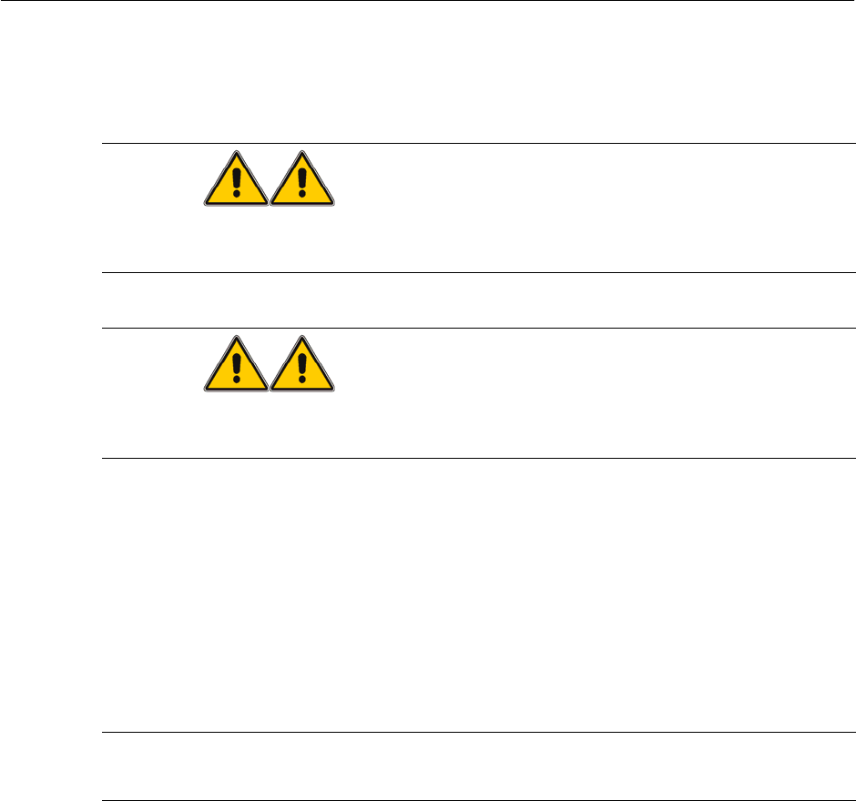
→ Open the cover of pneumatic compartment from the machine. Locate the air service unit
03039864-FS to frame of the machine as shown in Fig. 2.4.1-1. Fastened the knob to fix
the air service unit in position.
Figure 2.4.1-1 Installing Air Service Unit for AVSP Option
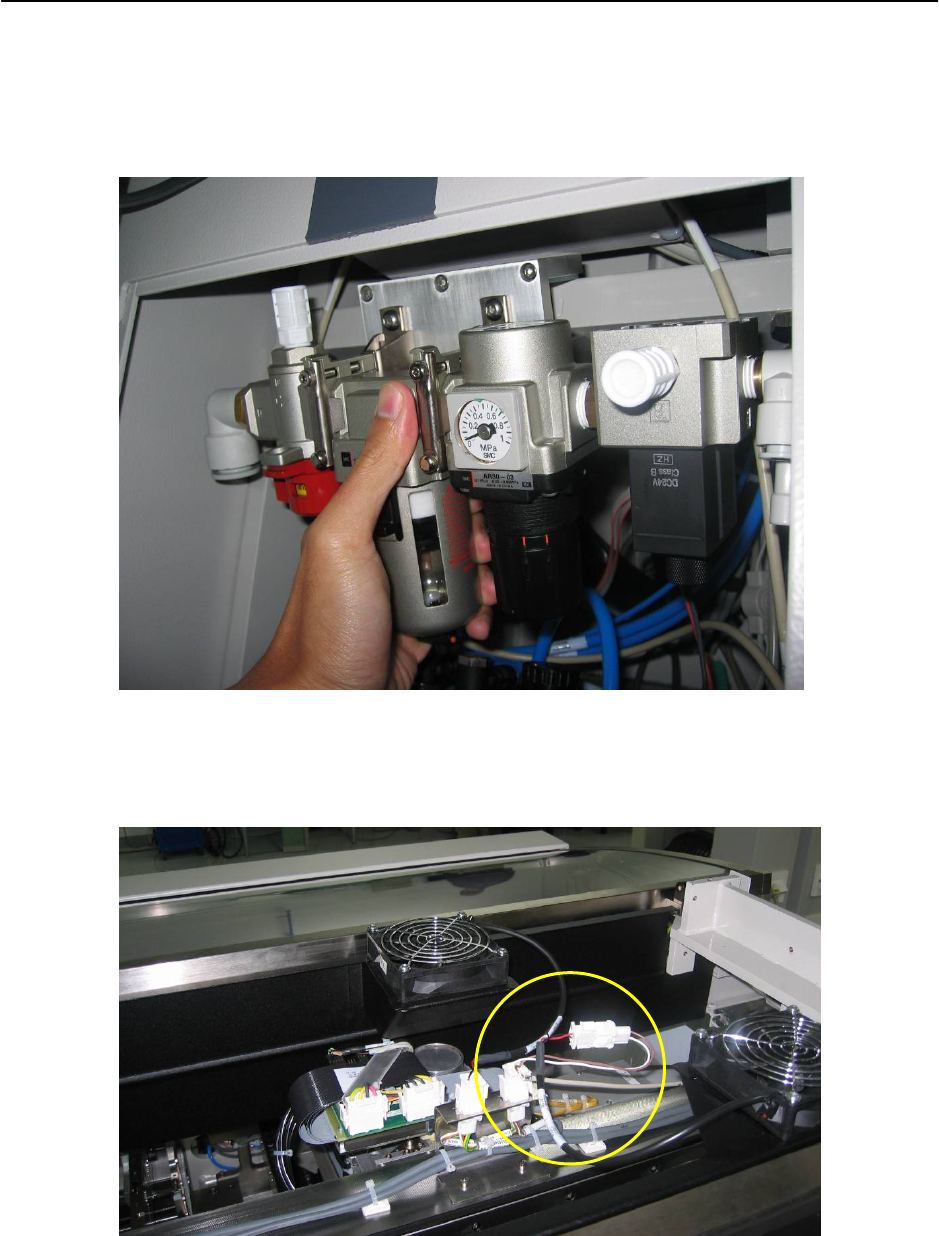
→ Tap power for solenoid valve on air service unit from exhaust fan from machine. Open
machine’s top cover to access. Connect as shown.
Figure 2.4.1-2 Tap power source from exhaust fan
2-15
Retrofit Instructions & User’s Manual / Automatic Vacuum Support Pins (AVSP)
Edition 04/2006
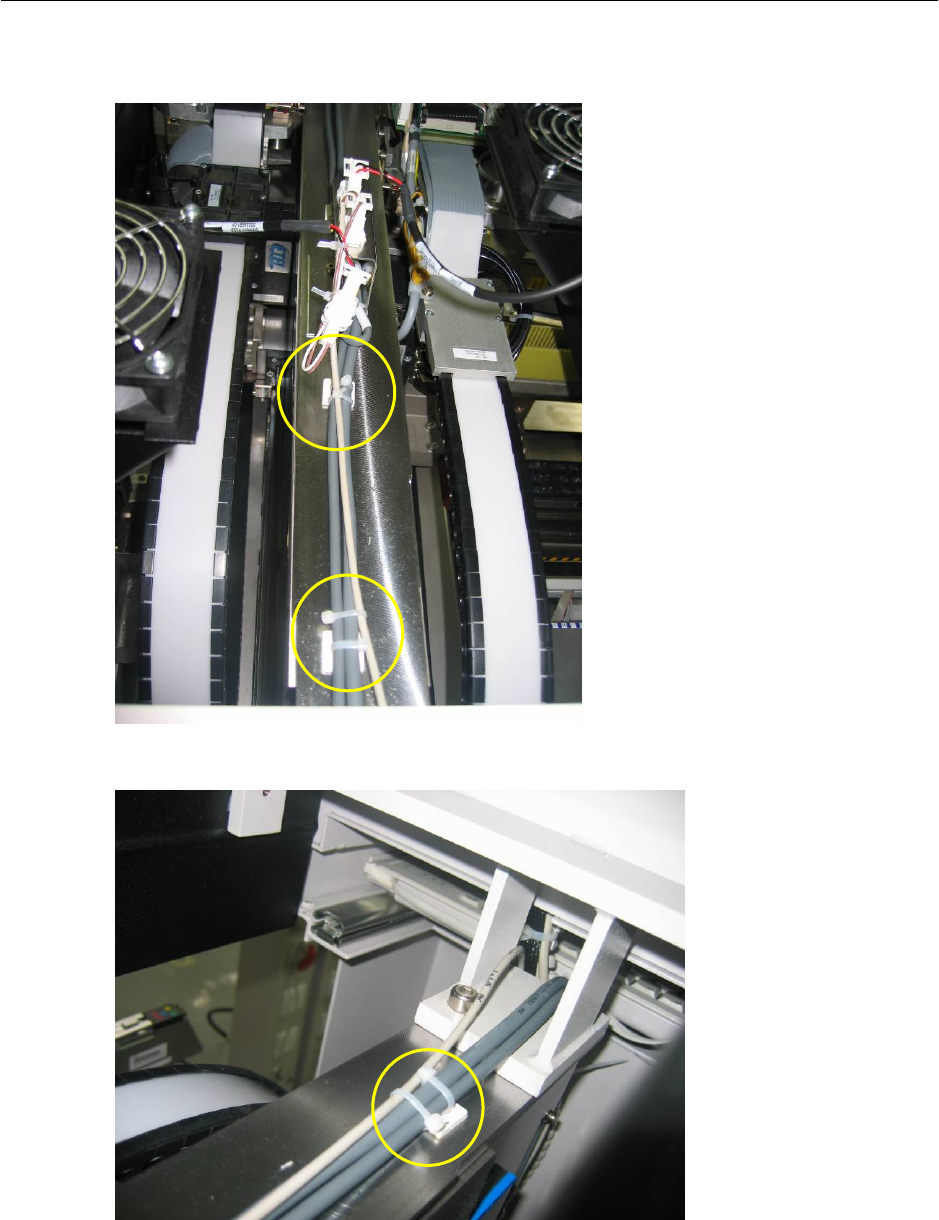
→ Lay cable neatly as shown below. Tie cable to existing cable using cable tie (Item No.:
00805140-FS) provided. Connect to the solenoid valve.
Figure 2.4.1-3 Lay power cable for solenoid valve
Figure 2.4.1-4 Lay power cable for solenoid valve
2-16