00194340-01.pdf - 第21页
Retrofit Instructions & User’s Manual / Automatic Vacuum Support Pins (AVSP) Edition 04/2006 Figure 2.4.1-5 Lay power cable for solenoid valve Figure 2.4.1-6 Tapping of compres sed air from machine 2-17
Retrofit Instructions & User’s Manual / Automatic Vacuum Support Pins (AVSP)
Edition 04/2006
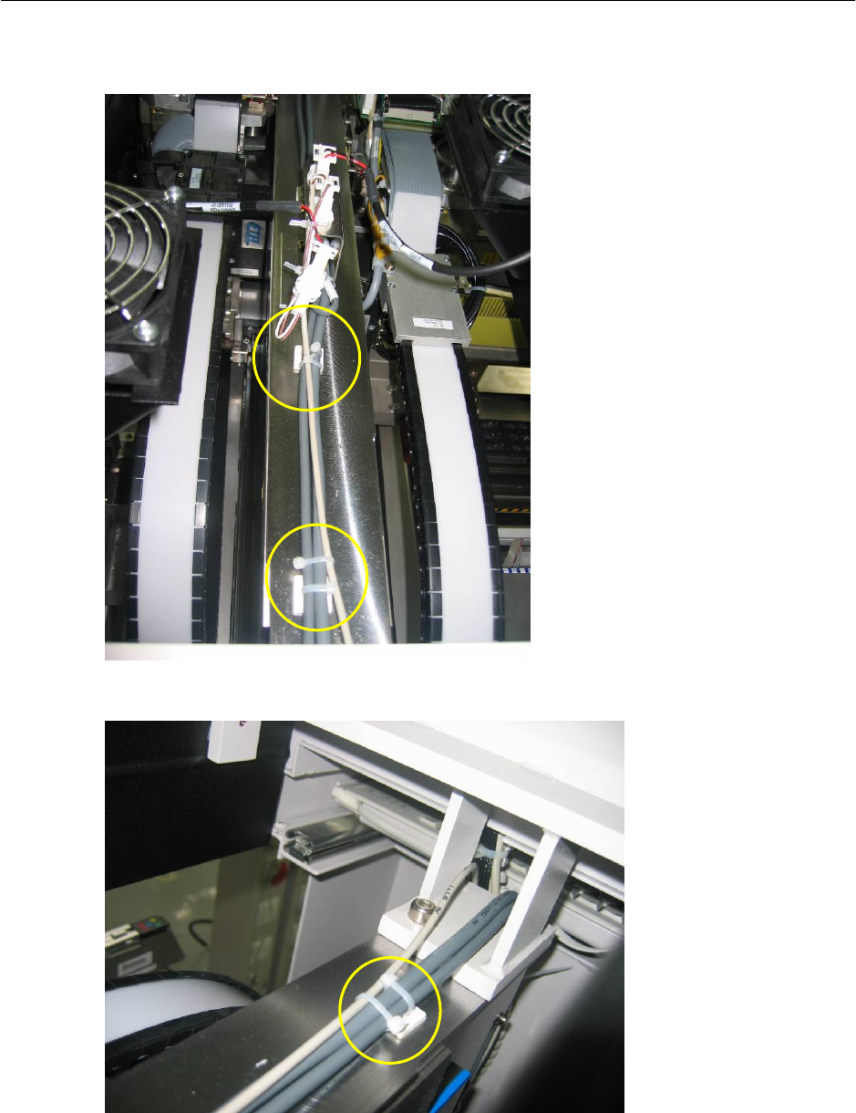
→ Lay cable neatly as shown below. Tie cable to existing cable using cable tie (Item No.:
00805140-FS) provided. Connect to the solenoid valve.
Figure 2.4.1-3 Lay power cable for solenoid valve
Figure 2.4.1-4 Lay power cable for solenoid valve
2-16
Retrofit Instructions & User’s Manual / Automatic Vacuum Support Pins (AVSP)
Edition 04/2006
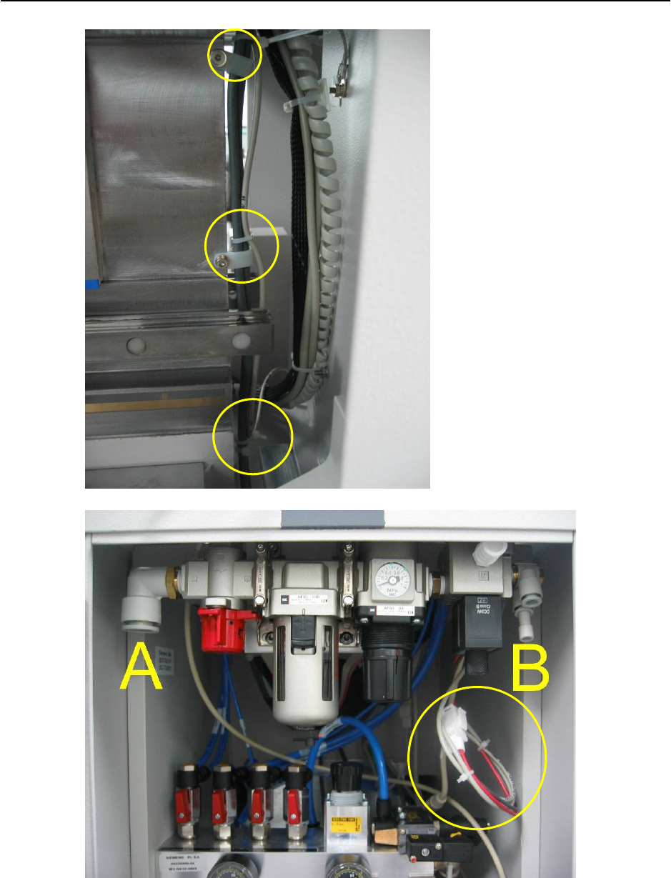
Figure 2.4.1-5 Lay power cable for solenoid valve
Figure 2.4.1-6 Tapping of compressed air from machine
2-17
Retrofit Instructions & User’s Manual / Automatic Vacuum Support Pins (AVSP)
Edition 04/2006
→ Connect air supply to inlet “A”, follow by turning “ON” the main valve. Adjust the pressure
to 5.5 bar.
→ Connect a tubing (Item No.: 03031461-FS) from port “B” and lay the tubing towards the
center of machine. The end of tubing should come out from the conveyor’s opening (as
shown in Figure 2.4.1-7) and it should be fitted with a T-Union (Item No.: 03031667-FS).
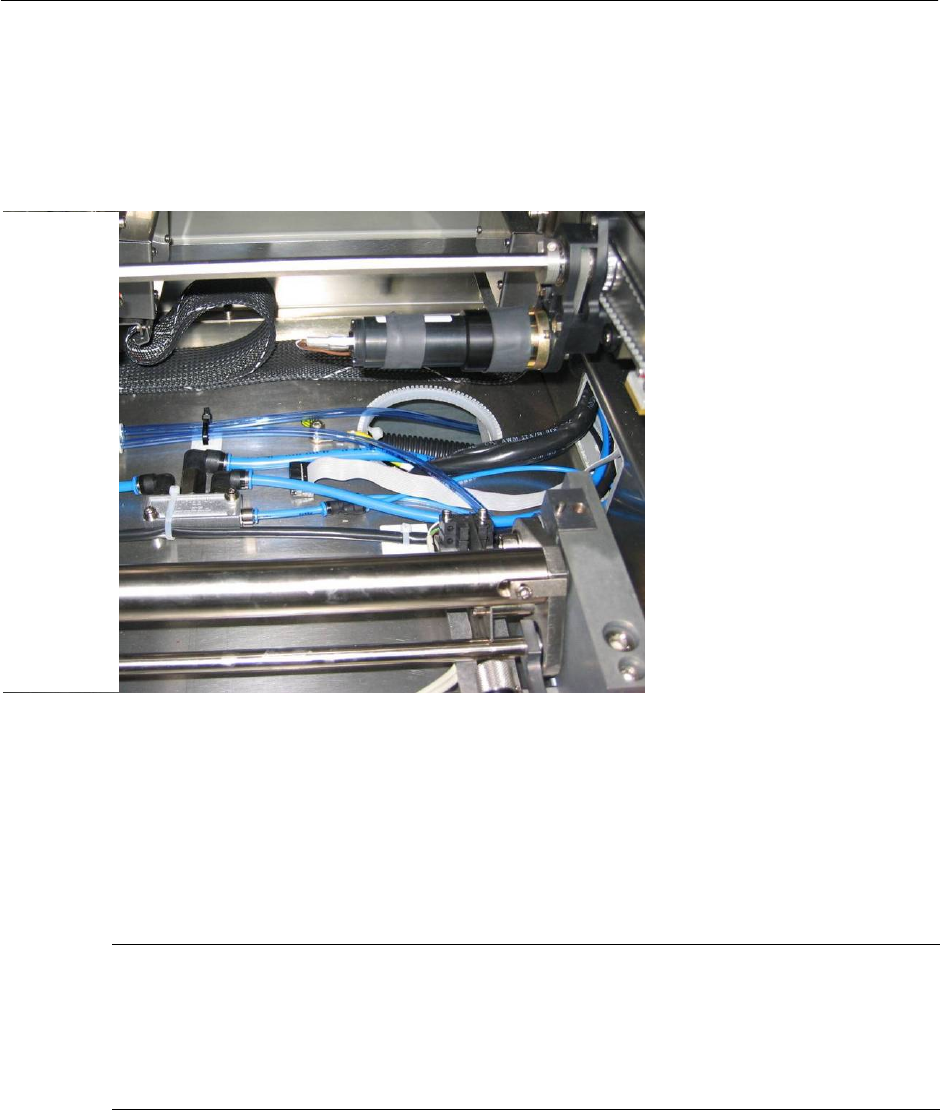
Figure 2.4.1-7 T-union branch for supply to 4 placement areas
→ From the T-union branch connector, run tubing to all the 4 placement areas as shown in
Figure 2.4.1-8 and at the end of the lines, fit with Y-Union (Item No.: 03031439-FS). Tie
up cablings together with the cable tie (Item No.: 00805140-FS) and bases (Item No.:
00318666-FS) provided.
NOTE
Branch connector allows air supply to four placement areas. However, if AVSP is not
necessary at all placement areas, laying of tubing can be skipped at the unused areas (E.g.
single conveyor). This will not affect the operation of used area. Plugs (03031441-FS) are
provided to shut off the extra ports on branch connector.
2-18