00194340-01.pdf - 第33页
Retrofit Instructions & User’s Manual / Automatic Vacuum Support Pins (AVSP) Edition 04/2006 2.5 Pin module installation → Adjust conveyor’s width to the exact width for PCB according to procedure s stipulated in use…
Retrofit Instructions & User’s Manual / Automatic Vacuum Support Pins (AVSP)
Edition 04/2006
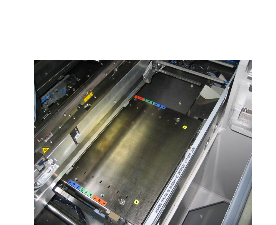
→ Mount the option plate on lifting table. Mounted option plate as shown in Figure 2.4.4-4.
→ Continue to assemble distributor on any other placement areas where AVSP is required.
→ Mount all dismounted lifting table top plate and PCB cover to its original location.
Figure 2.4.4-4 Mounted option plate
2-28
Retrofit Instructions & User’s Manual / Automatic Vacuum Support Pins (AVSP)
Edition 04/2006
2.5 Pin module installation
→ Adjust conveyor’s width to the exact width for PCB according to procedures stipulated in
user manual of SIPLACE HS-60. Make sure the width is at acceptable level by running
the PCB thru the whole conveyor length.
→ After adjusting the conveyor’s width, quit the session before installing the pin module.
Power OFF machine.
WARNING
Do not readjust the conveyor’s width once the pin module is installed. If readjustment is
necessary in any circumstances, remove the pin module(s) and tubing connected to it from
lifting table before adjustment.
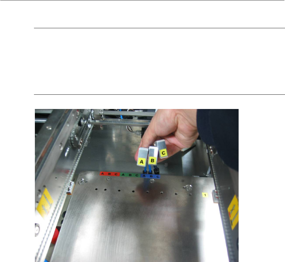
→ Connect the L-fitting on pin module (Item No.: 03031408-FS) to distributor. Make sure
ports are connected correctly according to the alphabet code.
WARNING
Misconnection of ports may result in pin module not functioning correctly and may caused
damaged to pin module.
2-29
Retrofit Instructions & User’s Manual / Automatic Vacuum Support Pins (AVSP)
Edition 04/2006
→ Adjust tubing length according to lane number where pin module(s) will be located.
NOTE
Tubing length need adjustment according to location the pin module is used on lifting table to
avoid interference to conveyor’s rail. Please refer Appendix 7.1 for recommendation of tubing
length. Color alphabetical coded option plate shown is meant to be a reference when table in
Appendix is used.
Up to maximum of 3 pin modules can be used on each placement areas.
Figure 2.5-1 Air interface tubing to pin module
2-30