00194340-01.pdf - 第37页
Retrofit Instructions & User’s Manual / Automatic Vacuum Support Pins (AVSP) Edition 04/2006 → Press machine’s stop button and open the respective machine’ s cover. If the gantry is in the way blocking the setting up…
Retrofit Instructions & User’s Manual / Automatic Vacuum Support Pins (AVSP)
Edition 04/2006
3 Operation instructions
3.1 Overview of operations
Upon full retrofit of AVSP on SIPLACE placement machine, AVSP can automatically adapt to
any PCB profile within a few steps.
teach the pin module
Users only need to
to adapt to the PCB profile using sample PCB.
The pin module can always be re-teach easily by following the similar steps.
3.2 PCB profile teaching operations
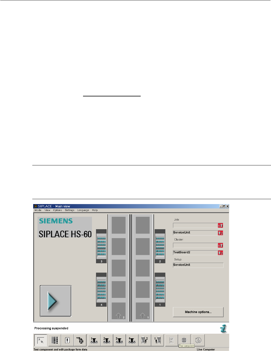
→ Turn ON machine power and you could see the SIPLACE main page on screen. Press
start key to reference run the machine.
NOTE
Turn air supply’s valve ON if you have shut OFF during retrofitting.
Reference run is a must for AVSP to functions correctly.
Figure 3.2-1 SIPLACE main page
3-32
Retrofit Instructions & User’s Manual / Automatic Vacuum Support Pins (AVSP)
Edition 04/2006
→ Press machine’s stop button and open the respective machine’s cover. If the gantry is in
the way blocking the setting up to be done, push it over to other location. You should see
the message “Close Cover” on the screen.
Figure 3.2-2 "Close Cover" message
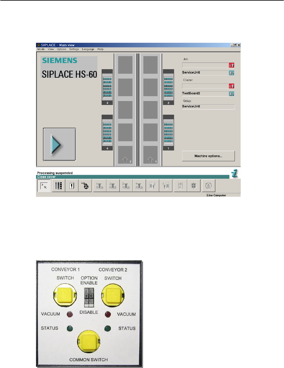
→ Turn the OPTION switch for respective placement area to “ENABLE”. Upon enabling the
option, for the first 2.5 second, the status LED will blink as to show booting up of AVSP.
The option is ready when the status LED turns ON continuously. AVSP automatically sets
itself to production mode by default (waiting for PCB).
Figure 3.2-3 Teach pendant button & status LED
3-33

Retrofit Instructions & User’s Manual / Automatic Vacuum Support Pins (AVSP)
Edition 04/2006
→ To go into teaching mode, press and hold on both the COMMON SWITCH and respective
CONVEYOR SWITCH simultaneously and the status LED will start blinking. Once the
status LED stops blinking, let go the switches.
NOTE
If both the switches is pressed too long (after the status LED stop blinking), AVSP returns to
production mode. The window to let go the switches once the status LED stop blinking is 2
seconds.
OR
If both the switches is let go too early (before the status LED stop blinking), AVSP returns to
production mode.
→ The pins are now released.
→ Press and turn the deactivation knob clockwise to unlock deactivated pins. Deactivate not
needed pins by pushing it to the lowest or fully extend those pins that are needed for
support. Some guidelines are listed below for proper setup of pins. (This step is optional,
can be skipped if correct pins configuration done previously.)
GUIDELINES FOR PIN SETUP
1. Use lesser pins possible to reduce contact force during teaching of PCB profile as long
as the number of support is enough for placement.
2. Replace end cap on pin(s) which is/are deactivated.
3. Use vacuum cup supplied on pin to reduce bouncing during placement.
4. For extreme thin board (less than 0.5mm thickness), teaching of PCB can be done by
feeding the PCB with an aluminum board.
5. Do not use vacuum cup with direct path of holes on PCB, regardless how small the hole
is.
3-34