00194340-01.pdf - 第40页
Retrofit Instructions & User’s Manual / Automatic Vacuum Support Pins (AVSP) Edition 04/2006 → Now close the machine’s cover and pre ss machine’s start button. → Go to conveyor’s single function. You would be able to…
Retrofit Instructions & User’s Manual / Automatic Vacuum Support Pins (AVSP)
Edition 04/2006
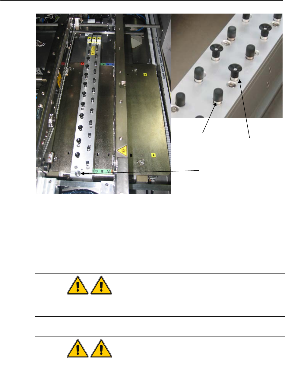
Vacuum
Cup
Deactivation
knob
End Cap
Figure 3.2-4 Deactivation knob, end cap and vacuum cup on pin module
→ Turn the deactivation knob counter-clockwise and lock the deactivated pin(s) in place.
→ Press and hold on both the COMMON SWITCH and respective CONVEYOR SWITCH
again and the status LED will start blinking. Once the status LED stops blinking, let go the
switches.
→ All pins are now reset to the lowest.
WARNING
Make sure all pins are reset to downward stroke and the STATUS LED is blinking slower
than the step before.
WARNING
Maximum component height allowed is 15mm. Make sure the PCB does not have any
component with height higher than 15mm. If there is, make sure the pin module(s) is away
from it.
3-35
Retrofit Instructions & User’s Manual / Automatic Vacuum Support Pins (AVSP)
Edition 04/2006
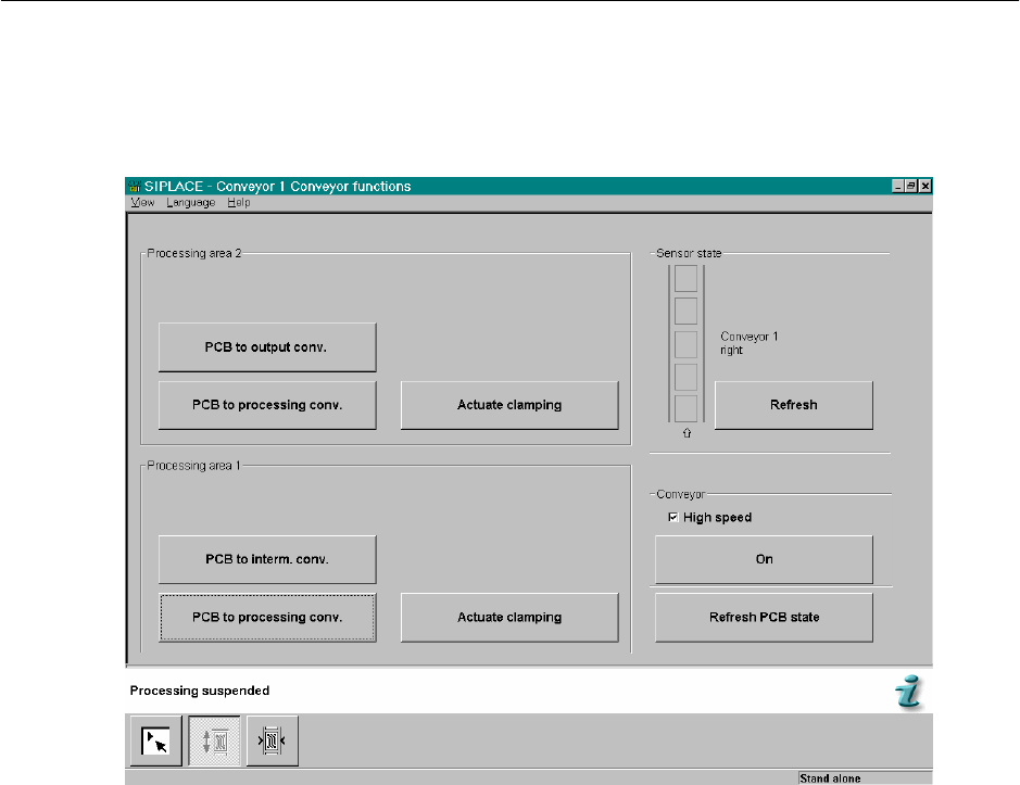
→ Now close the machine’s cover and press machine’s start button.
→ Go to conveyor’s single function. You would be able to page below.
Figure 3.2-5 Conveyor's single function
→ Feed in a sample PCB to the respective placement area and the pins will be raised up to
conform to PCB profile.
→ Feed out the sample PCB from machine. Teaching procedures completed and AVSP
goes back to production mode. Verify by checking the status LED turns on continuously.
→ Finally, feed in the same PCB to check if the support is satisfying.
3-36
Retrofit Instructions & User’s Manual / Automatic Vacuum Support Pins (AVSP)
Edition 04/2006
3.3 Production mode operations
By default when AVSP is turned ON, production mode is in operation. Only when the pre-
defined switch is activated, it will go into teaching mode.
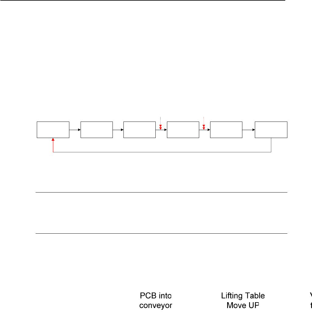
In production mode, AVSP will automatically provide support on PCB during the production
of components placement by moving the pin module up and down while switching the
vacuum ON and OFF to maximize PCB support. Below is the process sequence:
Figure 3.3-1 Production mode sequence
NOTE
The VACUUM LED on teach pendant turns ON if the vacuum supply falls below 300 mbar.
Check for leaking along the vacuum line (especially around the interface between vacuum
cups to PCB.
3-37