AQ-2 spec book LR - 第14页
General Specifica tions 12 of 44 2. 11 Board transport and positioning sys tem 2. 12 T rolley Interf ace T he transport unit moves the boards fr om the previous system into the run-in section of the AQ-2. Boards are then…
General Specifications
11 of 44
2.7 User
Interfaces
2.8 Adaptive
pick-up
2.9 Continuous
Calibration
Figure 8
2.10 Bad mark
sensing
Table 6
A user-friendly touch screen on the front of the machine supports most of the operator
instructions (e.g. start, stop, error recovery, etc.). A keyboard supports all functions and
maintenance features at supervising and maintenance level.
Pick-up point correction can be used to calibrate the exact position at which components
should be picked. This can be achieved by manual or automatic correction. Manual pick-
up-point sensing lets the operator place the head above the component and save the
current head position as pick position. Auto correction can be applied to any component
using the digital vision system, the component vision results (delta x, delta y) are stored
and used to modify the pick-up location.
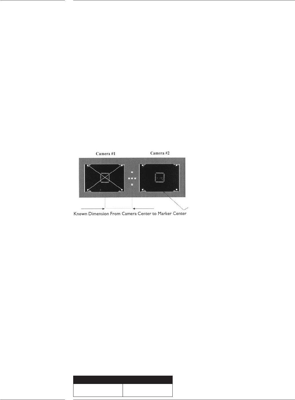
The AQ-2 System calibration is an on-line calibration that is performed automatically
with a reference plate each time a component is aligned.The glass reference plate, which
has a marker pattern on it, is fixed above the digital component alignment camera unit.
When the component camera system takes an image of a device, it automatically takes
an image of the reference pattern. Consequently the component camera system
measures the component with respect to this pattern.
Continuous calibration
Next to the placement head, the digital Board Alignment (BA) camera system is confi-
gured. At the same moment the component camera system takes an image of the
component and the reference pattern, the BA camera system takes an image of the head
marker as well. In this way the component position is measured with respect to the BA
camera system. Before component placement, the BA camera system has executed the
global board alignment which is used to relate the board coordinate system to the
machine coordinate system. Local fiducial or artwork alignment can be used to
determine more accurately where a fine-pitch component should be placed. This is
achieved by measuring an additional fiducial or artwork mark located near the
component placement position, prior to placement.
Bad mark sensing is used when multiple circuits are placed on one board. Markers that
contrast to the board surface can be used to identify circuits that do not need to be
assembled. The digital board alignment camera is used to scan these markers.
Components will not be placed onto circuits that have a bad mark present. The position
at which bad marks are located is programmable.
Optionally a master mark can be used. If this mark is present, it is assumed that one or
more circuits are bad, the AQ-2 will then scan all individual circuits. The position and use
of the master mark is programmable.
Bad marks
Minimum size >1mm

General Specifications
12 of 44
2.11 Board
transport
and
positioning
system
2.12 Trolley
Interface
The transport unit moves the boards from the previous system into the run-in section of
the AQ-2. Boards are then moved into the workarea where the boards are clamped and
held into position. After component placement, the board is transported to the next
assembly or process system.The standard transport system uses photoelectric sensors to
locate the substrate. An optional hard-stop is available for translucent or highly-
reflective substrates or materials.
The standard PCB transport can handle any board with a thickness ranging from 0.4mm
to 7 mm. The board size can vary from 50mm by 50mm upto 508mm by 460mm (LxW)
(maximum size is depending on configuration of the system) with a component free
zone of 3mm. The board is clamped into position by means of a lift unit that support the
boards from below. The lift unit can be equipped with adjustable support pins. The
second transport available is the Auer Boat transport which can handle boards with a
thickness of 0.4 mm to 11mm, with a component free zone of 5mm. Other specifications
are identical to the standard PCB transport.
It is also possible to handle boards with a minimum size of 50x20mm (LxW) or ultra thin
boards (down to 0.15mm thick) that require vacuum support. This option can be ordered
on special request.
Note: It is possible to change the direction of the board transport. Standard direction is
left to right. The AQ-2 machine can be used in production lines that run from right to left
but only in case the SMEMA electrical standard is used.
To add feeder trolleys, tray trolleys or feederbanks to the AQ-2, a trolley interface needs to
be mounted to the machine. One trolley interface enables two trolleys or banks to be
conected by the operator. With the introduction of the A-Series feeder trolley, two types
of trolley interfaces are available (See AQ-2 system tree for more information):
• A-Series trolley interface: This trolley interface can hold a combination of AQ-2 Tray
trolley, AQ-2 Feeder bank and A-Series feeder trolley. The A-Series feeder trolley can be
used on the A-Series platform. It is not possible to use the old style trolleys when the
A-Series trolley interface is mounted. Manual tray feeder and safety cover are available
on a project base. See AQ-2 system tree for more information.
• ACM Trolley interface:This trolley interface can hold a combination of the old style tray
trolley, feeder trolley, feeder bank, manual tray feeder and sector safety cover, as used
on ACM, AQ-1 and D-9. These trolleys cannot be used on the AX.
13 of 44
General Specifications
3.0 Options
3.1 Component
feeding
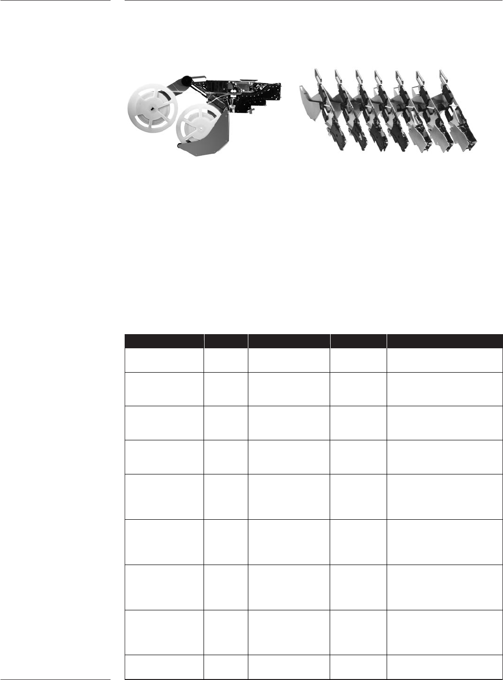
3.1.1 Tape Feeding
Feeder Width Pocket Depths Reels Pitches
PA 2657/00 8mm 3.5mm 7” – 13” 2, 4
(default)
PA 2654/06 8mm 12mm 7” – 13” 2, 4 (default)
(default) 8 - 56 pitch support
15” option available
PA 2654/16 12mm 12mm 7” – 13” 2, 4, 8, 12, 16, 20
(default) 24 ~ 56mm pitch
15” option support available
PA 2654/26 16mm 12mm 7” – 13” 2, 4, 8, 12, 16, 20
15.4mm option (default) 24 ~ 56mm pitch
15” option support available
PA 2654/36 24mm 12mm 7” – 13” 2, 4, 8, 12, 16, 20, 24
15.4mm option (default) 24 ~ 56mm pitch
15” option support available
22” option
PA 2654/46 32mm 12mm 7” – 13” 2, 4,8, 12, 16, 20, 24, 28, 32
15.4mm option (default) 36 ~ 56mm pitch
15” option support available
22” option
PA 2654/56 44mm 12mm 7” – 13” 2,4,8,12,16,20,24,
15.4mm option (default) 28,32,36,40,44
15” option 48~56mm pitch
22” option support available
PA 2654/66 56mm 12mm 7” – 13” 2, 4, 8, 12, 16, 20, 24,
15.4mm option (default) 28, 32, 36, 40, 44, 48,
15” option 52, 56
22” option
9466 920 10511 72mm 18mm 7” – 15” 4,8,12,16,20,24,
(default) 28, 32, 36, 40, 44, 48
Table 7
User benefits
•Twin Tape accommodates two 8mm tapes in a single feeder slot, enhancing the
support for family setup and increasing productivity.
• Intelligence eliminates incorrect feeder set-up, provides pre-empty reel warning and
is a basis for tracking and tracing.
• Single handed operation facilitates fast setup
• All-in-one feeder concepts; one feeder supports various reel sizes, pitches and tape
types reduce feeder inventory.
• Accurate component positioning and precise repeatability for maximum pick
performance
• Support from 72mm tapes to component down to 01005 for wide application support
• Supports splicing for uninterrupted production
• Support tapes based on the IEC 60286-3 specifications
Figure 9