AQ-2 spec book LR - 第15页
13 of 44 General Specifica tions 3.0 Options 3. 1 Component feeding 3. 1.1 T ape Feeding Feeder Width Pocket Depths Reels Pitches PA 2657/ 00 8mm 3.5mm 7” – 13” 2, 4 (default) PA 2654 / 06 8mm 12mm 7” – 13” 2, 4 (default…

General Specifications
12 of 44
2.11 Board
transport
and
positioning
system
2.12 Trolley
Interface
The transport unit moves the boards from the previous system into the run-in section of
the AQ-2. Boards are then moved into the workarea where the boards are clamped and
held into position. After component placement, the board is transported to the next
assembly or process system.The standard transport system uses photoelectric sensors to
locate the substrate. An optional hard-stop is available for translucent or highly-
reflective substrates or materials.
The standard PCB transport can handle any board with a thickness ranging from 0.4mm
to 7 mm. The board size can vary from 50mm by 50mm upto 508mm by 460mm (LxW)
(maximum size is depending on configuration of the system) with a component free
zone of 3mm. The board is clamped into position by means of a lift unit that support the
boards from below. The lift unit can be equipped with adjustable support pins. The
second transport available is the Auer Boat transport which can handle boards with a
thickness of 0.4 mm to 11mm, with a component free zone of 5mm. Other specifications
are identical to the standard PCB transport.
It is also possible to handle boards with a minimum size of 50x20mm (LxW) or ultra thin
boards (down to 0.15mm thick) that require vacuum support. This option can be ordered
on special request.
Note: It is possible to change the direction of the board transport. Standard direction is
left to right. The AQ-2 machine can be used in production lines that run from right to left
but only in case the SMEMA electrical standard is used.
To add feeder trolleys, tray trolleys or feederbanks to the AQ-2, a trolley interface needs to
be mounted to the machine. One trolley interface enables two trolleys or banks to be
conected by the operator. With the introduction of the A-Series feeder trolley, two types
of trolley interfaces are available (See AQ-2 system tree for more information):
• A-Series trolley interface: This trolley interface can hold a combination of AQ-2 Tray
trolley, AQ-2 Feeder bank and A-Series feeder trolley. The A-Series feeder trolley can be
used on the A-Series platform. It is not possible to use the old style trolleys when the
A-Series trolley interface is mounted. Manual tray feeder and safety cover are available
on a project base. See AQ-2 system tree for more information.
• ACM Trolley interface:This trolley interface can hold a combination of the old style tray
trolley, feeder trolley, feeder bank, manual tray feeder and sector safety cover, as used
on ACM, AQ-1 and D-9. These trolleys cannot be used on the AX.
13 of 44
General Specifications
3.0 Options
3.1 Component
feeding
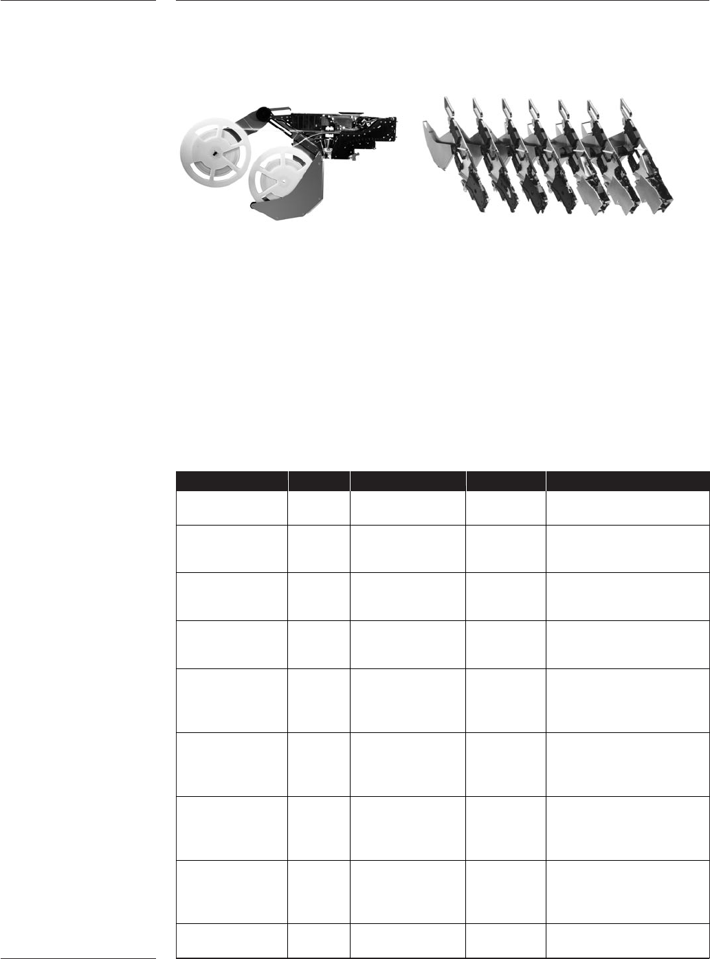
3.1.1 Tape Feeding
Feeder Width Pocket Depths Reels Pitches
PA 2657/00 8mm 3.5mm 7” – 13” 2, 4
(default)
PA 2654/06 8mm 12mm 7” – 13” 2, 4 (default)
(default) 8 - 56 pitch support
15” option available
PA 2654/16 12mm 12mm 7” – 13” 2, 4, 8, 12, 16, 20
(default) 24 ~ 56mm pitch
15” option support available
PA 2654/26 16mm 12mm 7” – 13” 2, 4, 8, 12, 16, 20
15.4mm option (default) 24 ~ 56mm pitch
15” option support available
PA 2654/36 24mm 12mm 7” – 13” 2, 4, 8, 12, 16, 20, 24
15.4mm option (default) 24 ~ 56mm pitch
15” option support available
22” option
PA 2654/46 32mm 12mm 7” – 13” 2, 4,8, 12, 16, 20, 24, 28, 32
15.4mm option (default) 36 ~ 56mm pitch
15” option support available
22” option
PA 2654/56 44mm 12mm 7” – 13” 2,4,8,12,16,20,24,
15.4mm option (default) 28,32,36,40,44
15” option 48~56mm pitch
22” option support available
PA 2654/66 56mm 12mm 7” – 13” 2, 4, 8, 12, 16, 20, 24,
15.4mm option (default) 28, 32, 36, 40, 44, 48,
15” option 52, 56
22” option
9466 920 10511 72mm 18mm 7” – 15” 4,8,12,16,20,24,
(default) 28, 32, 36, 40, 44, 48
Table 7
User benefits
•Twin Tape accommodates two 8mm tapes in a single feeder slot, enhancing the
support for family setup and increasing productivity.
• Intelligence eliminates incorrect feeder set-up, provides pre-empty reel warning and
is a basis for tracking and tracing.
• Single handed operation facilitates fast setup
• All-in-one feeder concepts; one feeder supports various reel sizes, pitches and tape
types reduce feeder inventory.
• Accurate component positioning and precise repeatability for maximum pick
performance
• Support from 72mm tapes to component down to 01005 for wide application support
• Supports splicing for uninterrupted production
• Support tapes based on the IEC 60286-3 specifications
Figure 9
General Specifications
14 of 44
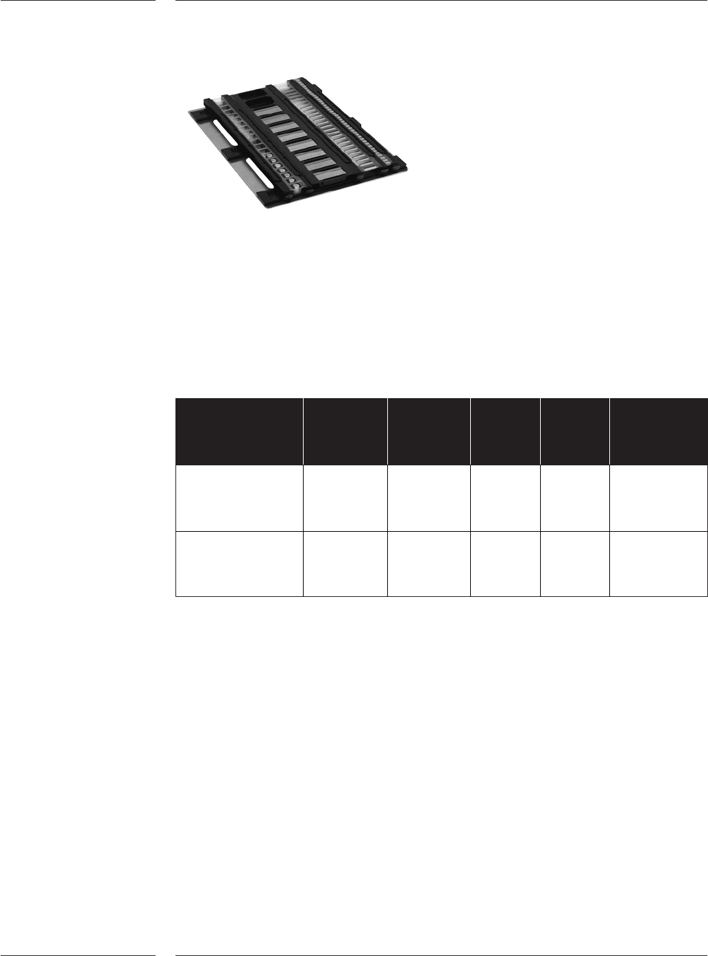
3.1.2 Carrier
tape trays
Figure 10
Table 8
User benefits
•Low cost, flexible solution for prototyping, evaluation, small batch and low volume
production
• Steady positioning of small pieces of carrier tape
• Support from 8mm to 200mm tapes
• Support of multiple tapes per lane
Feeder Lanes Tape Max Max Max Tapes
Width Tape Pocket per lane
Support Length Depth
9466 920 10501 8 6 x 8mm 318mm 3.5mm Multiple
2 x 12mm (1 up to 3
common)
9466 920 10591 Variable, 8mm to 324mm 10mm 1
default 200mm Optional: 2
= 4 *
* Note: Lanes can be extended by adding additional Tape Guides 9466 920 10601