AQ-2 spec book LR - 第38页
Placement output Co mponent placement 0 .68 sec./ comp or 5300 U PH uBGA, CSP , F lip Chip 1.02 sec./ comp or 3530 UPH IC placement 1.07 sec./ comp or 3350 UPH QFP placement 1.07 sec./ comp or 3350 UPH Odds & connect…
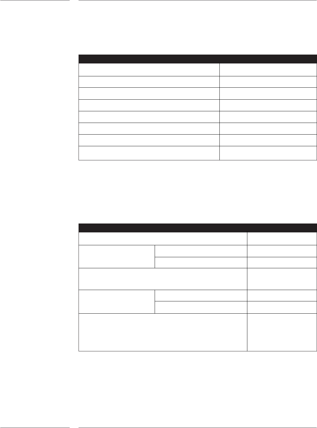
Placement accuracy & reliability
Placement process capacibility Cpk >1.33
Accuracy X,Y 25 µm @ 4 Sigma
Placement reliability < 3 ppm
Component pick performance > 99.9%
Machine stops < 500 ppm
Technical uptime > 99.5%
Average lifetime nozzle 2 million components
Average lifetime placement head 25 million components
4.0 Technical
specifications
4.1 Placement
accuracy &
reliability
Table 25
4.2 Flexibility
Table 26
Technical specifications
35 of 44
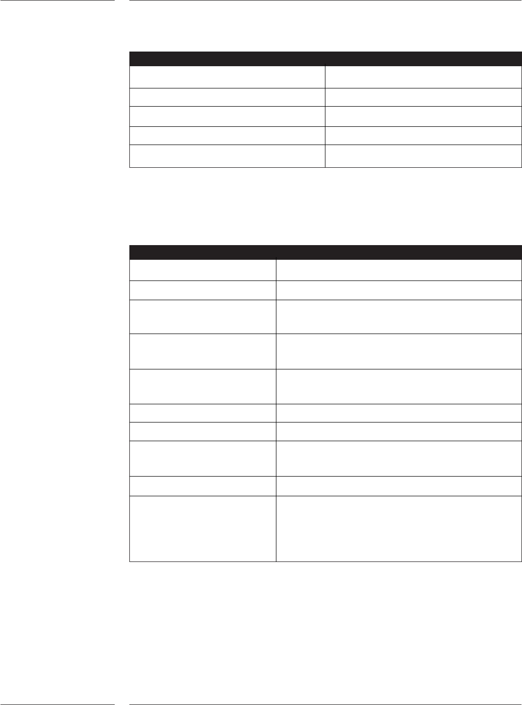
Flexibility
Feeder set-up change over < 3 min.
Exchange nozzle Manual < 30 sec.
Automatic via toolbit exchange < 1.5 sec.
Average time for generation placement programs
(can be done off-line) < 30 min.
Reconfiguring the system Toolbit exchange unit < 5 min.
Components vision unit < 5 min.
Amount of feeder positions max. 48 tape feeder
positions or max. 188
JEDEC trays
Note: Accuracy testing with glass plate, using the component vision (CV SFOV) and a CSP
of 6mm square (n=30) with process specification limit of 25 µm; all values are X, Y and
combined.
Placement output
Component placement 0.68 sec./comp or 5300 UPH
uBGA, CSP, Flip Chip 1.02 sec./comp or 3530 UPH
IC placement 1.07 sec./comp or 3350 UPH
QFP placement 1.07 sec./comp or 3350 UPH
Odds & connectors 1.07 sec./comp or 3350 UPH
Note: AQ-2 output is calculated at best conditions. This excludes board transfer, board
alignment and badmark sense times.
Circuit boards
Board size (max) (L x W) 508 x 460 mm
Board size (min) (L x W) 50 x 50 mm
Board thickness 0.4 - 7 mm for PCB transport
0.4 - 11 mm for Auer boat transport
Pre mounted components Top side: < 25 mm
Bottom side: < 45 mm
Typical board exchange time < 1.9 sec transport;
< 1.5 sec alignment (3 fiducials)
Tolerances L/W ±0.5mm
Maximum L/W-ratio 1/3
Flatness Topside: bow max 0.6% of diagonal to max 1 mm,
bottom side: sag max 5 mm
Mass < 3 kg
Clearance 3mm free of SMD’s at two sides parallel at
direction of transportation for PCB transport
5 mm free of SMD’s at two sides parallel at
direction of transportation for Auer boat transport
4.3 Placement
output
Table 27
4.4 Circuit
boards
Table 28
Technical specifications
36 of 44
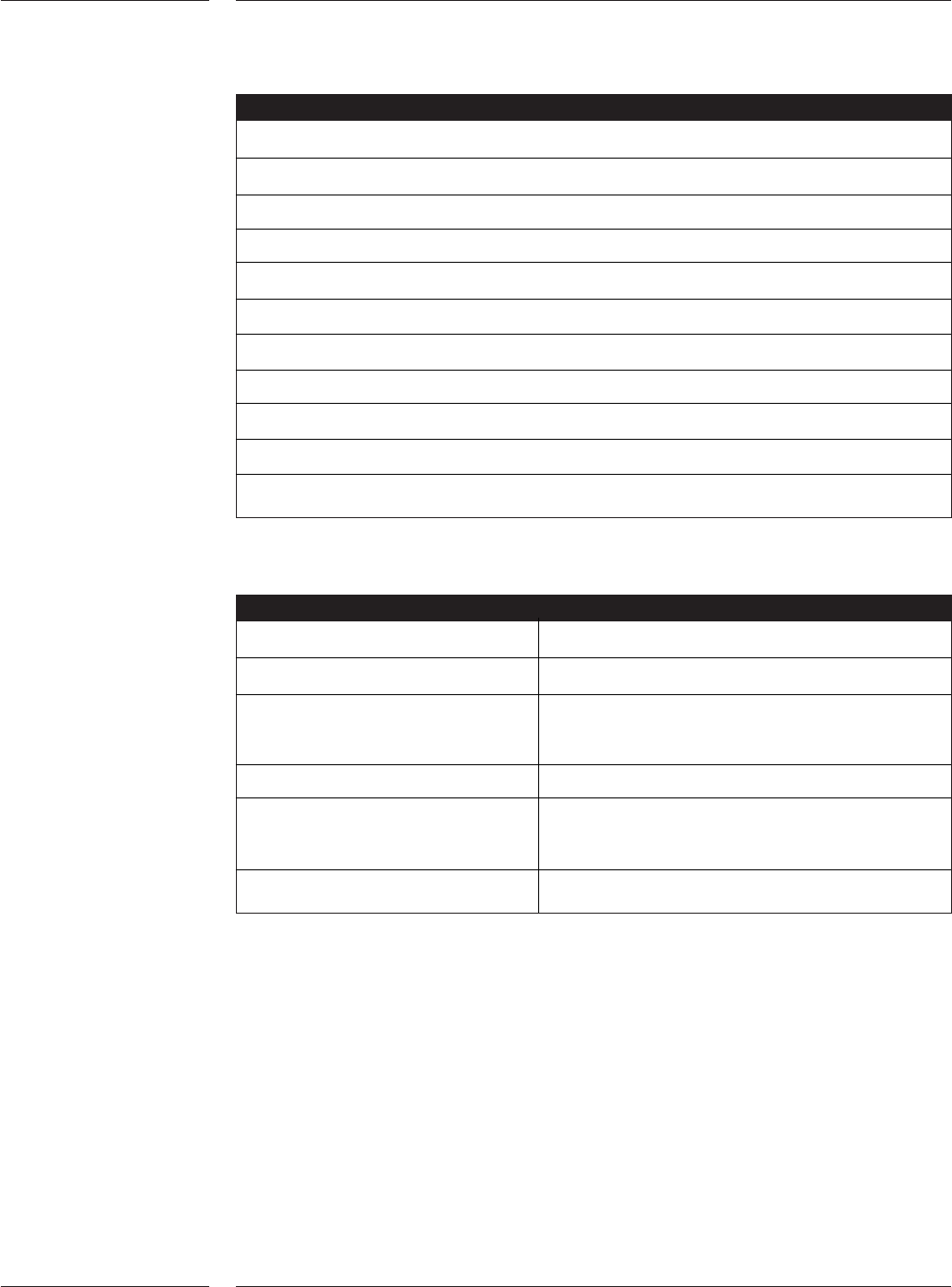
Standards
98/37/EC CE Machine directive
89/336/EEC CE EMC directive
73/23/EEC CE Low voltage directive
SEMI S2 Safety standard
SEMI S8 Ergonomics standard
SEMI E95 Human Interfaces standard
IPC 9850 Accuracy & speed testing standard
Cleanroom class 1000 (1k)
CAMX / XML interface
SECS / GEM interface (if software option is installed)
SMEMA compliant
4.5 Standards
Table 29
4.6 Components
Table 30
Technical specifications
37 of 44
Note: maximum component height without pre-mounted components
Components
SMD components 0201 up to QFP 45mm
Fine pitch components up to QFP 45mm (pitch > 0.3mm)
Odd components < 66 x 23mm (pitch > 0.3mm)
< 165 x 45mm
Grid arrays (BGA, MCM, etc.) up to 45mm (pitch > 0.5mm)
CSPs, uBGA, Flip Chips > 0.16mm pitch, > 0.08mm ball size,
Maximum number of balls: 3500
Component height up to 50mm