AQ-2 spec book LR - 第7页
C omponent vision •T wo upward looking digital camer as inspect components •C omponents are measur ed at placement height for optimal feature r ecognition • One camera unit covers the complete SM T component range • Came…
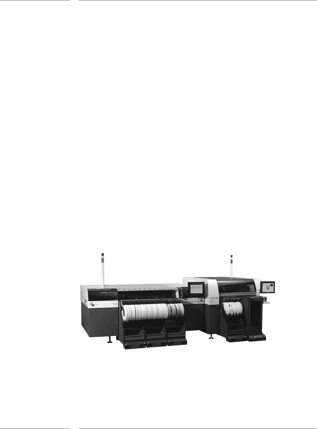
Figure 2
The AQ-2 digital vision system requires only two CCD-based component alignment
systems – LFOV and SFOV – to handle the entire range of components. Including light,
dark field, mid field and bright field illumination, the camera addresses the entire range
of leaded and array surface mount components. From a 45mm (1.8”) square IC with
0.15mm (0.006”) leads, to a 22mm (0.9”) square CSP with a bump diameter of 0.080mm
(0.003”) in a single field of view. Larger parts can also be mounted. The AQ-2 provides
unsurpassed vision capabilities. Considering the ability to combine the aforementioned
illumination styles with various levels of illumination intensity, the AQ-2 ensures the
optimal lighting scheme for any component from ceramic BGA to high reflective odd
components. Moreover, the component alignment system detects missing, bent, or
irregularly spaced leads and bumps; the machine places defective components into a
matrix reuse bin or simply dumps each into a bin.
Up to 94 8mm tapes in 48 twin tape feeders, or 188 JEDEC trays (or up to 376 other trays),
or a combination of 48 8 mm tapes and 94 JEDEC trays can be loaded on the AQ-2. The
open architecture allows the machine to employ feeders for tape, tube, tray and many
other feeder style, like GPAX feeders for odd form parts like USB Jacks or waffle pack
feeders for advanced array packages like CSPs. An off-line feeder set-up and rapid
product changeover is quickly achieved with the common A-Series feeder trolley system.
Operators easily exchange entire feeder banks to ensure a high level of machine
utilization. Additionally, the AQ-2 will automatically verify the trolley position and pick
height, then compensate accordingly to ensure repeatable positioning of the new feeder
module – another quick changeover and system stability feature of the AQ-2.
A controller, running a user-friendly Graphical User Interface allows manufacturers to
use the AQ-2 as a standalone machine or in-line with other production equipment. The
controller includes a Management Information System (MIS) that continuously gathers
production data for management feedback and performance tracking. The AQ-2 bad
mark sensing capabilities afford the use of board (global) and circuit (local) marks to
ensure that only good boards are populated.
A-Series flowline with AX-3 and AQ-2
The AQ-2 is fully compatible with the AX-series, which use the same feeder trolleys, tape
feeders and vision system. Ideally complementing the AX machine in medium to high
volume, low to high mix environment production, the A-Series line is suited for a wide
range of applications.
Introducing the AQ-2
4 of 44

Component vision
•Two upward looking digital cameras inspect components
•Components are measured at placement height for optimal feature recognition
• One camera unit covers the complete SMT component range
• Camera unit provides bump recognition down to 80 micron
• Variable red and blue lighting levels are combined for ideal feature recognition
H-Drive gantry system
• Provides the ideal combination of placement accuracy and process versatility
• Employs independent linear motors developed for the semiconductor industry
• Provides 25 micron @ 4 sigma placement accuracy
• Motor design eliminates drag, pull, and dog-tail effects
• Each of the three axes uses one-micron linear scale encoders
Placement heads
• Support nozzles and grippers
• Perform component pick detection and correction
• Automate pick height calibration
• Z-axis handles parts up to 50mm tall
• Placement force using closed loop feedback is programmable from 0.9 to 40N
Feeder platform
• Feeder trolley allows 47 pick positions in 24 8mm slots
• Tray trolley handles over 96 unique Jedec tray-fed components or 188 other tray
components
• Feeder bank provides an interface for SMT and oddform feeders
Transport unit
• Three types of transport are available to support very thick boards, regular PCBs, and
ultra-thin flexfoils
• Uses edge clamping or vacuum support
• Features automatic board width and thickness adjustment
• Boards are individually edge belt driven
Graphical User Interface
• Touchscreen interface with intuitive icons
• On-line component editor
• Optional multiple language support
Open architecture
• Allows cost-effective purchase of options for the current application
• Supports addition of modules in the field for new applications
• Each module uses fiducials to ensure quick installation and calibration in minutes
1.1 Features
Introducing the AQ-2
5 of 44

2.0 General
Specifications
2.1 AQ-2
Specifications
Table 1
General Specifications
6 of 44
AQ-2 Main Specifications
Max output [CpH] 5300
Max output for odds [CpH] 3350
Max output for ultra fine pitch [CpH] 3530
Highest Accuracy class 25µm @ |µ|+4 (Cpk>1.33)
Pick performance 99,9 %
Technical Uptime > 99.5% (excl. feeder assists)
Lifetime: Nozzle > 2 Mio placements
Component range 0.4x0.2mm (01005) to 45x45mm or 66x23mm
For odds up to 165 x45mm
Feeding options Feeder trolley: 47 pick positions
Tray trolley: 96 JEDEC trays
Feeding types Tape, stick, tray, wafflepack, stack tube, GPAX,
radial etc .
Placement force 0.9N to 40N, lower forces with restrictions
PCB range min ( L x W ) 50x50mm L=PCB transport direction
50x20mm
optional
PCB range max ( L x W ) 508x460mm L=PCB transport direction
PCB transport direction Left to Right or Right to Left.
Power supply 190-480V 3-phase
47-63Hz, 5 kVA
Air supply >6bar, 190 Nl/min
Dimensions (incl. trolleys) 1560x2380m(LxW) Total 3.71 m
2
Weight (excl. trolleys) <1750kg
Noise <72 dB(A) @ 1m distance
Applicable standards: 98/37/EC CE Machine directive
89/336/EEC CE EMC directive
73/23/EEC CE Low voltage directive
SEMI S2 Safety standard
SEMI S8 Ergonomics standard
SEMI E95 Human Interfaces standard
IPC 9850 Accuracy & speed testing standard