AQ-2 spec book LR - 第9页
General Specifica tions 7 of 44 2.2 Machine b ase 2.3 H-Drive man ipu lat or F igure 3 T he machine base is an H-shaped frame constructed out of welded standard rectangular steel plates. It consists of a set of two verti…
2.0 General
Specifications
2.1 AQ-2
Specifications
Table 1
General Specifications
6 of 44
AQ-2 Main Specifications
Max output [CpH] 5300
Max output for odds [CpH] 3350
Max output for ultra fine pitch [CpH] 3530
Highest Accuracy class 25µm @ |µ|+4 (Cpk>1.33)
Pick performance 99,9 %
Technical Uptime > 99.5% (excl. feeder assists)
Lifetime: Nozzle > 2 Mio placements
Component range 0.4x0.2mm (01005) to 45x45mm or 66x23mm
For odds up to 165 x45mm
Feeding options Feeder trolley: 47 pick positions
Tray trolley: 96 JEDEC trays
Feeding types Tape, stick, tray, wafflepack, stack tube, GPAX,
radial etc .
Placement force 0.9N to 40N, lower forces with restrictions
PCB range min ( L x W ) 50x50mm L=PCB transport direction
50x20mm
optional
PCB range max ( L x W ) 508x460mm L=PCB transport direction
PCB transport direction Left to Right or Right to Left.
Power supply 190-480V 3-phase
47-63Hz, 5 kVA
Air supply >6bar, 190 Nl/min
Dimensions (incl. trolleys) 1560x2380m(LxW) Total 3.71 m
2
Weight (excl. trolleys) <1750kg
Noise <72 dB(A) @ 1m distance
Applicable standards: 98/37/EC CE Machine directive
89/336/EEC CE EMC directive
73/23/EEC CE Low voltage directive
SEMI S2 Safety standard
SEMI S8 Ergonomics standard
SEMI E95 Human Interfaces standard
IPC 9850 Accuracy & speed testing standard
General Specifications
7 of 44
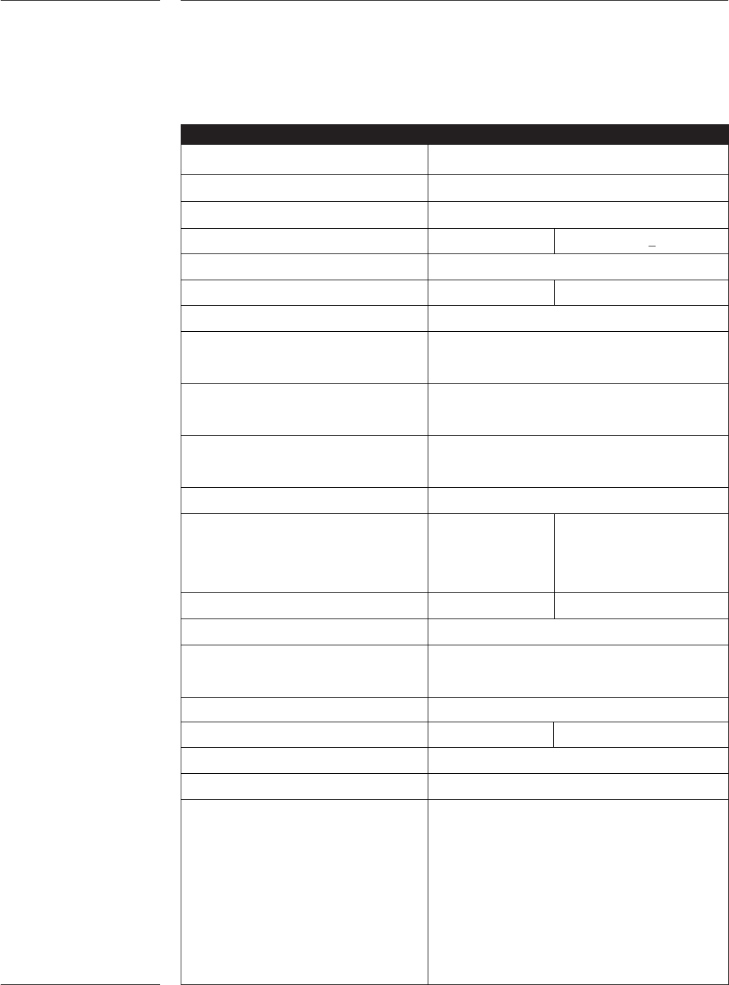
2.2 Machine base
2.3 H-Drive
manipulator
Figure 3
The machine base is an H-shaped frame constructed out of welded standard rectangular
steel plates. It consists of a set of two vertical box structures, connected by a horizontal
square box structure. The frame is rigid and stable to minimize vibration transfer from
the factory-floor to the machine. Adjustment of the frame to the floor can be done
during or after installation. The transport height level complies to both SMEMA and
Japanese standards.
The machine base contains all mechanical interface surfaces for connection of the robot,
feeders trolleys/banks and PCB transport. It also holds the control and supply systems as
well as the safety covers and doors to provide safe working conditions for the operator.
The H-Drive manipulator is a self-calibrating Cartesian robot with linear motors and
encoders. The manipulator has two Y-axes and one X-axis, each with their own
integrated controller and power stages. Special attention is given to the dynamic
behaviour of the manipulator which is of great importance for the performance. Settling
times are defined as the period between the end of the setpoint profile and the moment
that the manipulator actually reaches the required position. If the position window is
chosen smaller (e.g. for fine pitch components, requiring higher accuracy) the settling
time will be longer. For the H-Drive manipulator, a cubic setpoint profile will be used. In
a cubic setpoint profile the acceleration gradually increases and decreases as function of
time. The X-slide of the manipulator has, on the front side, an interface which is
configured with 2 placement heads and 1 digital fiducial camera.
H-Drive manipulator
H-Drive manipulator
Resolution X and Y motor 1 micron
Acceleration X motor 17 m/s
2
Acceleration Y motors 12 m/s
2
Velocity X motor 1.4 m/s
Velocity Y motors 1.4 m/s
Max. stroke X motor 660mm
Max. stroke Y motors 1140mm
Table 2
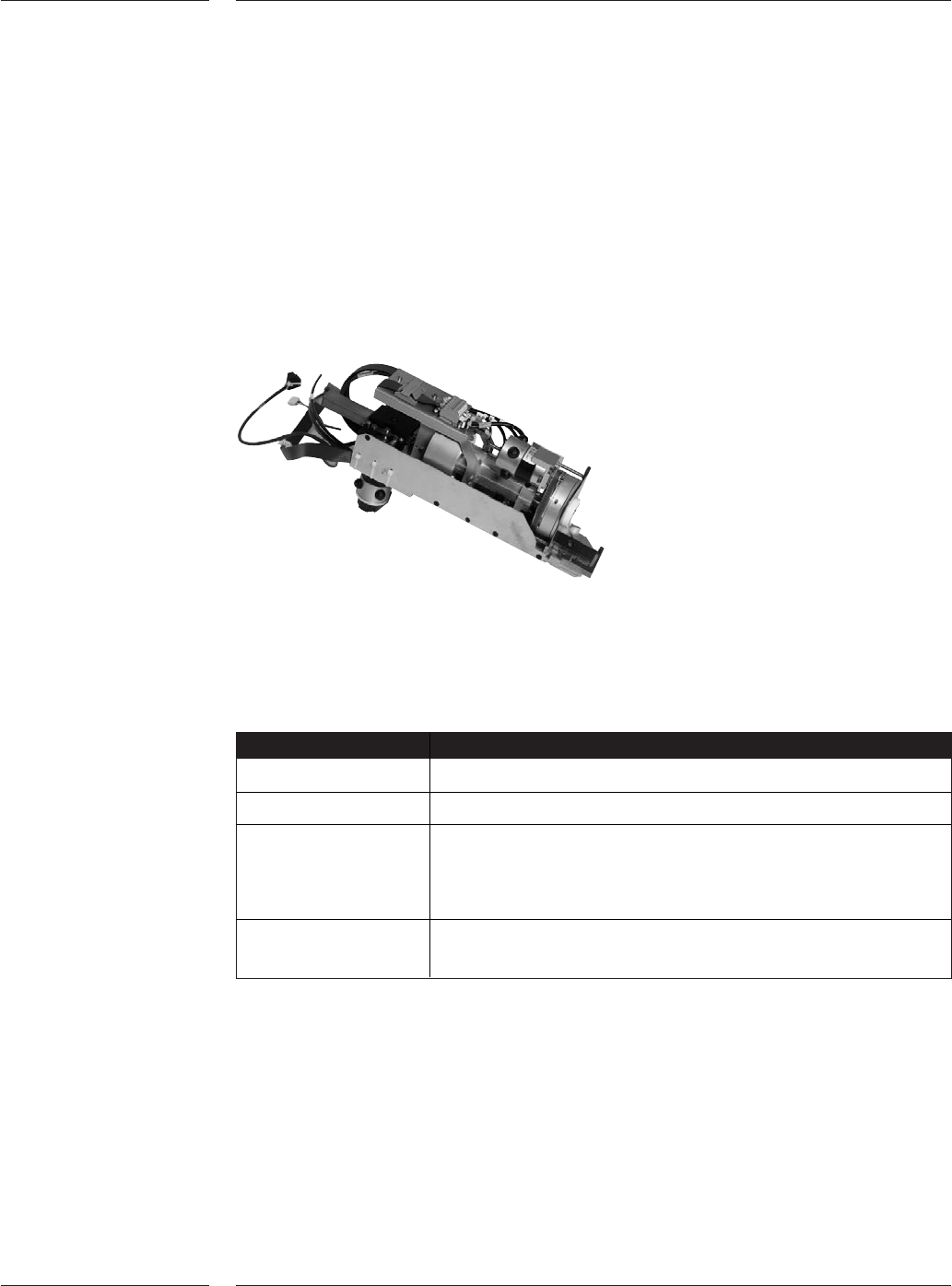
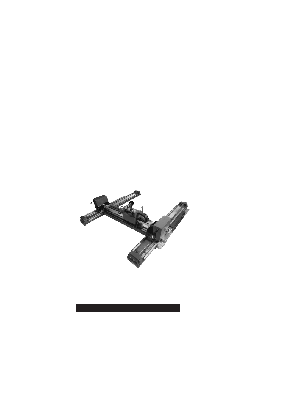
2.4 Placement
head
Both placement heads are equipped with Z-height, phi-rotation and real time force
control. It can pick, rotate and place any component within the work area of the AQ-2.
Component pick-up and detection is done using a vacuum nozzle or a gripper.
Component presence as well as the relative position will be checked by the component
vision system. When placing through-hole components the AQ-2 can detect bent leads
using “variable through hole check”. If leads are bent the placement head will measure a
resistance force when a lead touches the PCB. If the force exceeds the programmable
limit (between 4 and 14 N) the AQ-2 will reject the component. Nozzles and grippers can
be automatically exchanged with the toolbit exchange unit configured on the machine
base between feeder interface and workarea.
Placement head
General Specifications
8 of 44
Figure 4
Maximum stroke 77mm
Phi resolution 0.0072 degree
Placement force Inner nozzles: 1.5N ± 0.3N (Fixed)
Outer nozzles: 4-40N (programmable in 0.1N increments)
Flip chip nozzles: 0.9-3.5N (programmable in 0.1N increments)
Variable through hole Programmable between 4 and 14 N
check
Placement head
Table 3