Istruzioni d´uso_HF3_14_it.pdf - 第615页
22 2KE0041502 - englisch_BA 04.1 1.2010 ENGLISH 1 0 . OPERA TION OF CONTROL AND OPERA TING UNIT The process cooler is switched on by means of the power disconnect switch (main switch) which also doubles as EMERGENCY STOP…
21
2KE0041502 - englisch_BA
04.11.2010
ENGLISH
6.2 Refrigeration Circuit
After the activities on the water circuit have been completed, the motor protecting switches of
the compressors have to be placed to the -1- position (see circuit diagram in the appendix).
Acknowledge all fault messages that may be signalled on the control panel.
The process cooler is not operational, the control and operating unit takes over the control of
the water outlet temperature.
Check set-point settings and change, if necessary.
7. DECOMMISSIONING
The safety notices contained in Chapter 1 must be complied with !
Disconnect process cooler from power supply.
Completely drain water circuit, including tank, pump(s), pipes and filters
(see flow diagram of pipes and instruments in the appendix)
Take freeze protection measures (consult manufacturer)
8. SHUTDOWN IN EMERGENCIES
The safety notices contained in Chapter 1 must be complied with !
Turn power disconnect switch (main switch) on the process cooler to „off“
9. ENVIRONMENTAL REQUIREMENTS
When repairing or placing the process cooler out of service (decommissioning), the
environment-relevant requirements regarding recovery, reuse and disposal of fuels/oils and
components according to DIN EN 378 are to be complied.
The operator of the process cooler is responsible for the proper disposal of used fuels,
oils and system components.
The disposal of the water containing additives is to be effected in agreement with the
competent local authorities.
7. Decommissioning
8. Shutdown in Emergencies
9. Envirnomental Requirements
22
2KE0041502 - englisch_BA
04.11.2010
ENGLISH
10. OPERATION OF CONTROL AND OPERATING UNIT
The process cooler is switched on by means of the power disconnect switch (main switch)
which also doubles as EMERGENCY STOP switch.
The process cooler is now operational, the control and operating unit takes over the control of
the water outlet temperature.
It is not possible to start up the unit if there is an active low water level or dry run protection
signal.
10. Operation of Controland Operating Unit
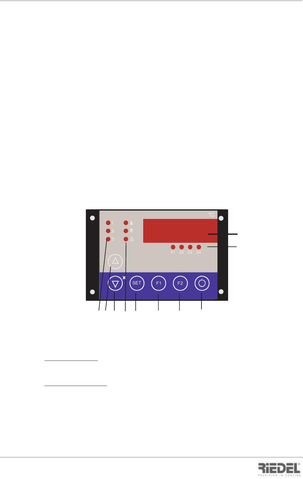
10.1 Control and Operating Unit ST 501
1 Display
2 Status displays
E1 Pump+water level status
E2 High pressure status
E3 Low pressure status
E4 TK fan status
3 Control modes
1 Pump on
2 Control setting 1 on
3 Control setting 2 on
4 UP button
to increase setpoint or parameter value
5 DOWN button
to decrease setpoint or parameter value
Actual values
Version with tank:
In the normal state, the flow temperature of the water circuit is indicated on the display.
Version without tank:
In the normal state, the return temperature of the water circuit is indicated on the display.
Press button F2 to display the flow temperature.
Setpoint adjustment
The setpoint is adjusted by simultaneously pressing the SET button and the UP or DOWN
button.
1
2
3
SET
E1
E2 E3
E4
F1
F2
°C
1
2
3 4 5 6 7 8 9 10
Control and Operating Unit ST 501
6 Alarm displays
Arrow Up“ fixed setpoint control, upper
limit value, f. differential control
„Arrow Down“ fixed setpoint control,
lower limit value, f. differential control
„Alarm“ common fault alarm
7. SET call-up of setpoint or parameter
display
8 F1 button -> special function after
parameter enabling
9 F2 button -> special function after
parameter enabling
10 Stand-by button controller On / Off
Option
23
2KE0041502 - englisch_BA
04.11.2010
ENGLISH
11. MAINTENANCE
The safety notices contained in Chapter 1 must be complied with !
Always disconnect the process cooler from the mains power supply before attempting
to open the cabinet !
No specific refrigeration technology knowledge is required for the performance of maintenance
activities. This work can be carried out by a properly trained person with appropriate know-how.
11. Maintenance
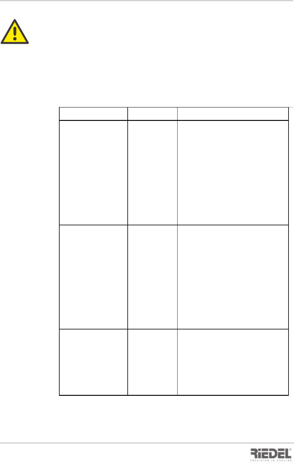
Item to be serviced Interval Activity
Process cooler
in general
Phone: +49 (0) 9221 / 709-545
Fax: +49 (0) 9221 / 709-529
Water circuit
Cooling water
- Replace filter or clean, if necessary
- Check water quality
Cooling air circuit
Filter mat
Condenser
2 weeks
2 weeks
1 week
- Visual inspection of air filter mat for
contamination
- Visual inspection of refrigeration circuit
for leaks
- in the event of leaks, call customer
service:
- Visual inspection of water circuit for
leaks
Clean condenser with compressed air, be
careful not to damage fins
- Check water level, top up
Replace filter mat or clean, if necessary
Filter in
water circuit