00197543-01_SM_JTF-S_ JTF-M_en - 第19页
Service Works 2.1.5 Control-Board JTF-M_Pos1100 [03111983-xx] and Control-Boa rd JTF- S_Pos1090[03111984-xx], Daughter Board _ Pos300 [0311174 4-xx] Service Manual SIPLACE JEDEC Tray Feeder 19 2.1.5 2 . 1 . 5 C o n t r o…
Service Works
Interfaces / Communications / Magazine 2.1.4 SIPLACE JTF-M Communication [03111983-01 _ Pos1100]
18 Service Manual SIPLACE JEDEC Tray Feeder
EPROM details:
▪ EPROM version for SIPLACE JTF-S: A25-05-4.0.6
▪ Material number (Order number) Contol PCB including EPROM: 03111984-01
Description: Control PCB Assy JTF-S_9036240 (Pos 1090)
The daughterboard _Pos300 [03111744-xx] has to be ordered separately.
2.1.4
2.1.4 SIPLACE JTF-M Communication [03111983-01 _ Pos1100]
SIPLACE JTF-M Communication [03111983-01 _ Pos1100]
The SIPLACE JTF-M feeder is handled like a Waffle Pack Changer (WPC5/6). Different components can
be set up for each JEDEC Tray (14 or 18 JEDEC Trays).
The control panel is completely deactivated by the SIRIO Software. The communication protocol is HEX-
Command.
On the control board in the feeder is a label on the EPROM, which identifies the software version.
EPROM details:
▪ EPROM Version for SIPLACE JTF-M: A26-06-ASM1.3
▪ Material number (order number) Control PCB including EPROM: 03111983-01
The daughterboard_Pos300 [03111744-xx] has to be ordered separately.
Description:
EPROM JTF3 Control PCB Assy JTF-M_9036241 (Pos 1100)
The SIPLACE JTF-M is fully controlled from the SIRIO-Software via HEX-Communication. Therefore the
control panel on the SIPLACE JTF-M is automatically deactivated. Only the RESET button will be re-
leased automatically from the SIRIO-Software in case of a hardware error.
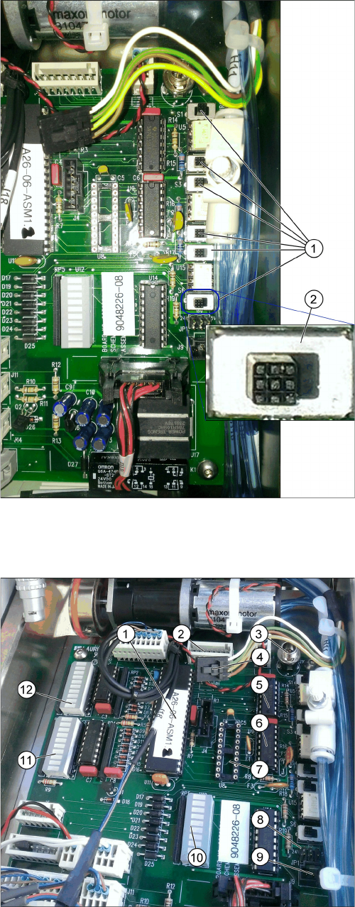
Location EPROM
1. U3 - Position of EPROM on the Control PCB
2. Daughterboard
Service Works
2.1.5 Control-Board JTF-M_Pos1100 [03111983-xx] and Control-Board JTF-S_Pos1090[03111984-xx], Daughter Board _ Pos300 [03111744-xx]
Service Manual SIPLACE JEDEC Tray Feeder 19
2.1.5
2.1.5 Control-Board JTF-M_Pos1100 [03111983-xx] and Control-Board JTF-S_Pos1090[03111984-xx], Daughter Board _ Pos300 [03111744-xx]
Control-Board JTF-M_Pos1100 [03111983-xx] and Control-Board JTF-
S_Pos1090[03111984-xx], Daughter Board _ Pos300 [03111744-xx]
The SIPLACE JTF-S and the SIPLACE JTF-M have a daughterboard plugged to the control board.
This board transfers the communication protocol from the SIPLACE interface to the SIPLACE JTF-
Standard.
Also, the power supply from the X-FCU 30V is converted to the 24V of the SIPLACE JTF-Standard.
Part numbers:
▪ Control-Board JTF-M_Pos1100 including EPROM [03111983-xx]
▪ Control-Board JTF-S_Pos1090 including EPROM [03111984-xx]
▪ DAUGHTER BOARD ASSY RS-232, JTF2_9039470 (Pos300) [03111742-01]
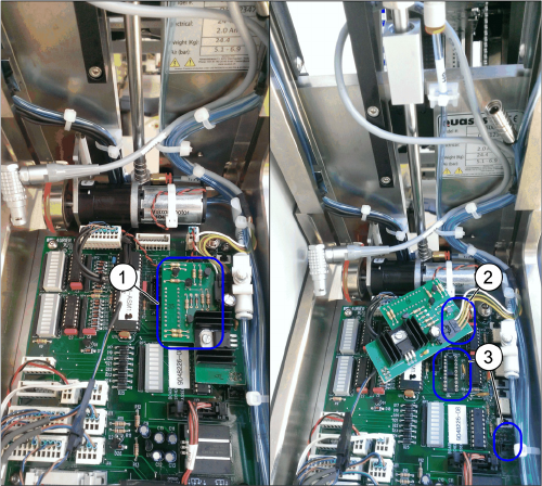
Control PCB with daughterboard
1. Daughterboard
2. ASM host cable connected to J1 on the daughter-
board
3. Daughterboard connected to socket U8 and JP1 of
the control PCB
Service Works
Interfaces / Communications / Magazine 2.1.5 Control-Board JTF-M_Pos1100 [03111983-xx] and Control-Board JTF-
20 Service Manual SIPLACE JEDEC Tray Feeder
2.1.5.1
2.1.5.1 Detailed description of control board and daughterboard
Detailed description of control board and daughterboard
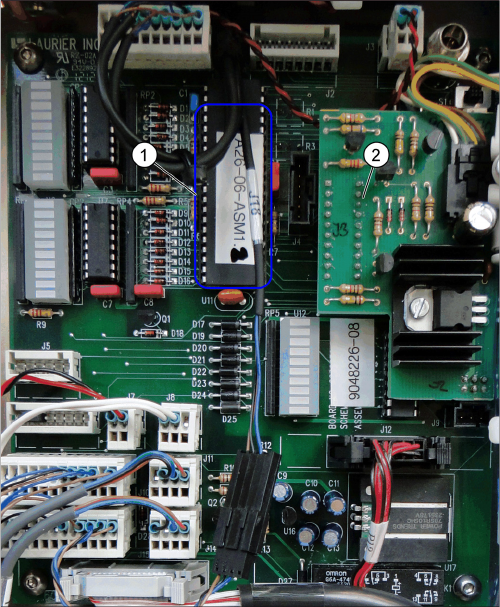
Dip switches on control PCB
There are some Dip switches on the control PCB, which
are not used. They have to be set on Off (2):
▪ Dip-switch off (sink) (1), like shown in the picture.
Control board detail
1. U3 – EPROM
2. J2 – Host
3. J16 – Auxiliary power connector
4. J1 – Connector from Lemosa / FCU, will be connect-
ed to daughterboard and supplies power (30V/GND)
and signal (RX/TX).
5. U4 – Motor Driver IC [03111678-01] (Pos30 Mo-
tordriver IC U4 of control PCB_2034101)
6. U9 – Motor Driver IC [03111675-01] (Pos20 Mo-
tordriver IC U9 of control PCB_2033989)
7. U8 – Connector for J3 from daughterboard (control
signals)
8. JP1 – Converted power (24V/GND) will be supplied
from daughterboard (J2)
9. J9 – Serial RS232 (not used)
10. U12 – Feeder output bank
11. LED status bar U6
12. LED status bar U1