00197543-01_SM_JTF-S_ JTF-M_en - 第24页
Service Works Overview SIPLACE JTF-Sections 2.1.6 Magazine 24 Service Manual SIPLACE JEDEC Tray Feeder 2.2 2 . 2 O v e r v ie w S I P L A C E J T F - S e c t io n s Overview SIPLACE JTF-Sections A SIPLACE JTF-Feeder can …
Service Works
2.1.6 Magazine Interfaces / Communications / Magazine
Service Manual SIPLACE JEDEC Tray Feeder 23
2.1.6.2
2.1.6.2 Magazine for SIPLACE JTF-M
Magazine for SIPLACE JTF-M
The SIPLACE JTF-M loads or unloads trays out of a magazine. There currently are two magazines avail-
able:
▪ 14 slots (thick trays or sheets) [00166673-xx]
▪ 18 slots (thin trays or sheets) [00166672-xx]
Loading Sequence of SIPLACE JTF-M tray magazine
► Move down the elevator to refill position with in the SIRIO menu.
► Open the loading door.
► Unlock the Tray lock 1 and Tray lock 2.
► Check the proper direction of the magazine. The arrow on top shows the direction the magazine has
to be inserted in the SIPLACE JTF-M.
► If the magazine is inserted in the wrong direction, the SIPLACE JTF-M will be unable to count the
magazine slots through the magazine slot detection slits and recognize the magazine is empty.
► Slide the magazine onto the elevator bars.
► Close the loading door.
► If the loading door cannot be closed, the JEDEC trays may be orientated wrong.
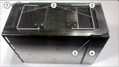
JTF-M Tray Magazin
1. Arrow for feeding direction of the magazine
2. Magazine handles
3. Magazine slot detection slits
4. Tray lock 1
5. Tray lock 2
Service Works
Overview SIPLACE JTF-Sections 2.1.6 Magazine
24 Service Manual SIPLACE JEDEC Tray Feeder
2.2
2.2 Overview SIPLACE JTF-Sections
Overview SIPLACE JTF-Sections
A SIPLACE JTF-Feeder can be split into two main sections:
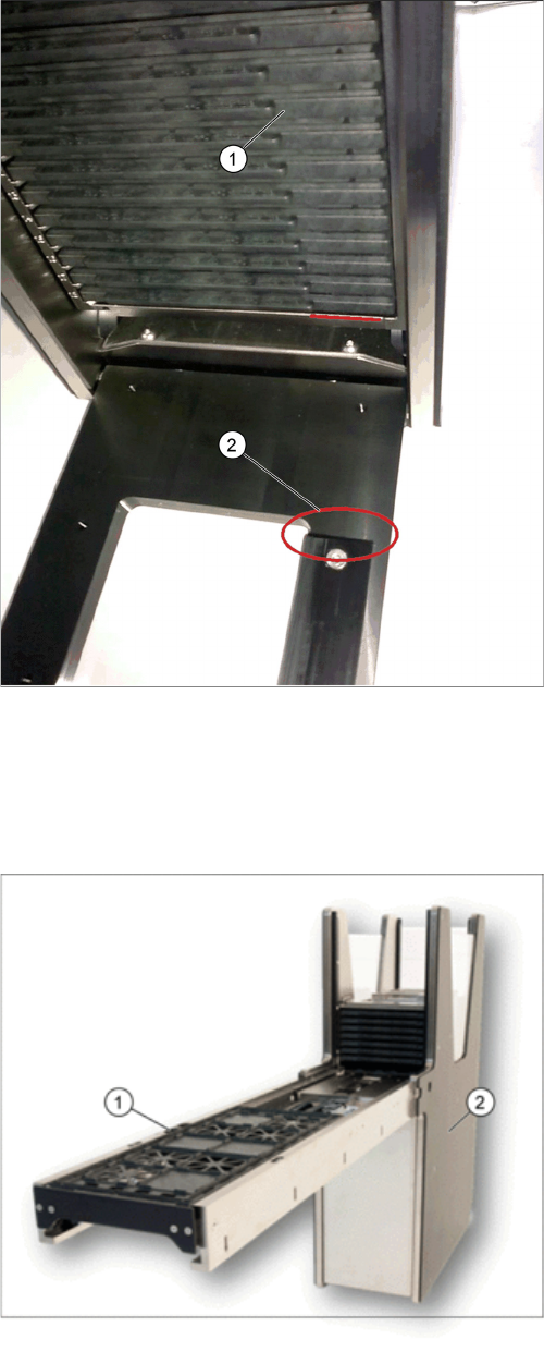
SIPLACE JTF-M door lock orientation key
1. Tray magazine orientation
2. Tray orientation bar
JTF- main sections
1. Base section (tower)
2. Conveyor section
Service Works
2.2.1 Dismounting Conveyor Section from Base Section Overview SIPLACE JTF-Sections
Service Manual SIPLACE JEDEC Tray Feeder 25
2.2.1
2.2.1 Dismounting Conveyor Section from Base Section
Dismounting Conveyor Section from Base Section
2.2.1.1
2.2.1.1 Disconnect Control Board
Disconnect Control Board
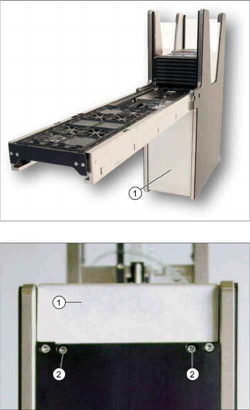
Remove cover
Front cover screws
► Remove cover (1) by releasing two front cover
screws (2) at the bottom of the base to have access
to the control board.