00197543-01_SM_JTF-S_ JTF-M_en - 第25页
Service Works 2.2.1 Dismounting Conveyor Secti on from Base Section Overview SI PLACE JTF-Sections Service Manual SIPLACE JEDEC Tray Feeder 25 2.2.1 2 . 2 . 1 D is m o u n t in g C o n v e y o r S e c t io n f r o m B a …
Service Works
Overview SIPLACE JTF-Sections 2.1.6 Magazine
24 Service Manual SIPLACE JEDEC Tray Feeder
2.2
2.2 Overview SIPLACE JTF-Sections
Overview SIPLACE JTF-Sections
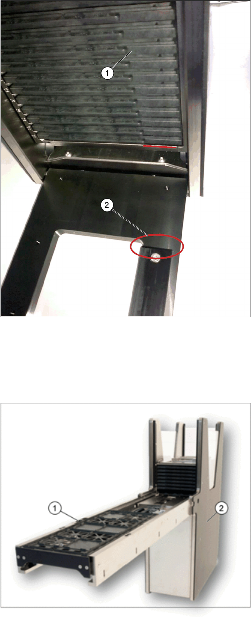
A SIPLACE JTF-Feeder can be split into two main sections:
SIPLACE JTF-M door lock orientation key
1. Tray magazine orientation
2. Tray orientation bar
JTF- main sections
1. Base section (tower)
2. Conveyor section
Service Works
2.2.1 Dismounting Conveyor Section from Base Section Overview SIPLACE JTF-Sections
Service Manual SIPLACE JEDEC Tray Feeder 25
2.2.1
2.2.1 Dismounting Conveyor Section from Base Section
Dismounting Conveyor Section from Base Section
2.2.1.1
2.2.1.1 Disconnect Control Board
Disconnect Control Board
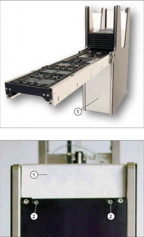
Remove cover
Front cover screws
► Remove cover (1) by releasing two front cover
screws (2) at the bottom of the base to have access
to the control board.
Service Works
Overview SIPLACE JTF-Sections 2.2.1 Dismounting Conveyor Section from Base Section
26 Service Manual SIPLACE JEDEC Tray Feeder
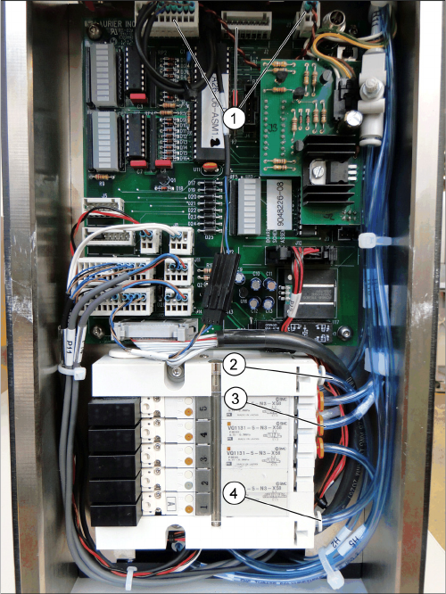
Disconnect control board
► Disconnect all cables and unplug at connectors J1,
J2, J3 and J18, cut cable ties where needed (1), in
case J9 needs to be disconnected as well.
► Disconnect all tubes from the solenoid valve block at
H7, H8, H9 and H10 (3).
► Disconnect all tubes from the air pressure regulator
(2) and air pressure check tube (4).
► The valve block is different between SIPLACE JTF-S
(5 blocks, as seen in picture "Disconnect control
board") and SIPLACE JTF-M (3 blocks).