00197543-01_SM_JTF-S_ JTF-M_en - 第29页
Service Works 2.3.1 Replacing Conveyor Belts ( SIPLACE JTF-S / SIPLACE JTF-M) S ervice Conveyor Unit Service Manual SIPLACE JEDEC Tray Feeder 29 2.3.1.1 2 . 3 . 1 . 1 R e p la c in g C o n v e y o r B e lt R ig h t [ 0 3…
Service Works
Service Conveyor Unit 2.2.2 Remove Side Covers from Base Unit
28 Service Manual SIPLACE JEDEC Tray Feeder
2.2.2
2.2.2 Remove Side Covers from Base Unit
Remove Side Covers from Base Unit
Both side covers must be removed from the base unit to get access to all mechanics and sensors in the
side plates (“ears”).
2.3
2.3 Service Conveyor Unit
Service Conveyor Unit
2.3.1
2.3.1 Replacing Conveyor Belts (SIPLACE JTF-S / SIPLACE JTF-M)
Replacing Conveyor Belts (SIPLACE JTF-S / SIPLACE JTF-M)
Used parts:
▪ Conveyor belt 1.27 x 9.65 x1646, Right_15001060 (Pos 50) [03111679-xx]
▪ Conveyor belt 1.27 x 9.65 x1680, Left_15001061 (Pos 60) [03111680-xx]
The JEDEC Tray Feeder must be prepared according to the maintenance and replacement procedures
to perform the retrofit of the belts.
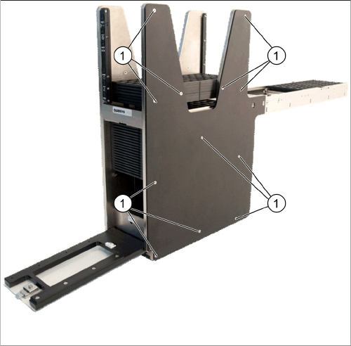
Remove side cover
► Remove all twelve sink screws (1) from the side cov-
er.
► If access is required, do this also on the other side.
Service Works
2.3.1 Replacing Conveyor Belts (SIPLACE JTF-S / SIPLACE JTF-M) Service Conveyor Unit
Service Manual SIPLACE JEDEC Tray Feeder 29
2.3.1.1
2.3.1.1 Replacing Conveyor Belt Right [03111679-01] (Pos 50)
Replacing Conveyor Belt Right [03111679-01] (Pos 50)
2.3.1.2
2.3.1.2 Replacing Conveyor Belt Left [03111680-01] (Pos60)
Replacing Conveyor Belt Left [03111680-01] (Pos60)
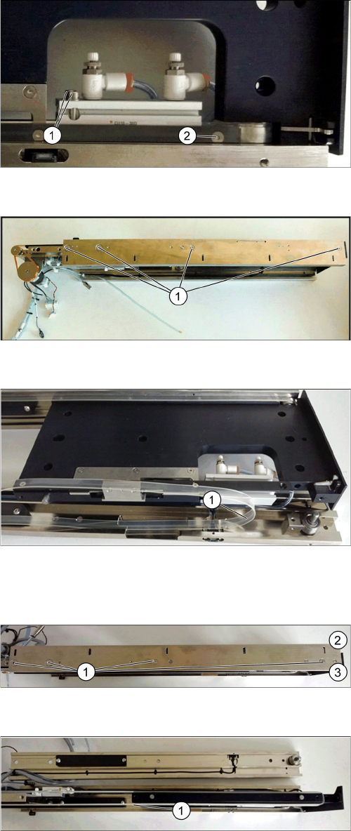
Remove Tray Clamp Screw Right Side
► Remove the Tray Guide Screw (1).
► Remove the two cylinder mounting screws (2).
Conveyor Remove Right Side
► Remove four screws (1) holding the conveyor rail.
► Take off the right conveyor rail from the conveyor
base.
Replace Belt Right Side
► Replace the conveyor right belt (1) by using the Con-
veyor belt 1.27x9.65x1646, Right_15001060
[03111679-01]. Be aware that the right belt and the
left belt do have different lengths.
► Reinstall the Conveyor Rail Right Side in reverse se-
quence.
Remove mounting screws conveyor left
► Remove the four screws (1) at the conveyor left rail.
Opposite view in picture - Bottom (2) and top (3).
Replace belt left side
► Remove the left conveyor rail.
► Replace the conveyor left belt (1) by using the Con-
veyor belt 1.27x9.65x1680, Left_1500106
[03111680-01]. Be aware that the right belt and the
left belt do have different lengths.
► Reinstall the conveyor rail left side in reverse se-
quence.
Service Works
Service Conveyor Unit 2.3.2 Tray Clamp Foot Replacement [03111693-01] (Pos150)
30 Service Manual SIPLACE JEDEC Tray Feeder
2.3.2
2.3.2 Tray Clamp Foot Replacement [03111693-01] (Pos150)
Tray Clamp Foot Replacement [03111693-01] (Pos150)
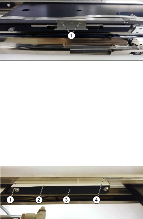
The following procedure documents how to replace tray clamp foot.
► Remove the right side rail as described under chapter "2.3.1 Replacing Conveyor Belts (SIPLACE
JTF-S / SIPLACE JTF-M)" [ ➙ 28].
► Remove the two sink screws (1) holding the clamp foot on the bracket.
► Install a new tray clamp foot and reassemble the conveyor.
2.3.3
2.3.3 Belt Guide Block Installation and Adjustment
Belt Guide Block Installation and Adjustment
The following instructions explain how to install and adjust the belt guide blocks on the
SIPLACE JTF-M feeder.
The guide blocks are attached to the rail by two M4 x 16 button head cap screws (3).
The size of the mounting holes is 5.56 millimeters (.219 inches) allowing the block to be positioned ac-
cordingly so parts do not jump out of the tray during convey.
► To set the guide block position height, place a 0,38 mm (.015 inches) shim (2) between the belt (1)
and the rail (4), push the guide block up while tightening the mounting screws.
1. Sink screws
Guide Blocks
1. Conveyor belt
2. 0.015” shim (0.38mm) between the belt and conveyor
rail
3. Guide blocks with M4 x 16 button head screws
4. Conveyor rail