00197543-01_SM_JTF-S_ JTF-M_en - 第34页
Service Works Service Base Unit 2.4.2 Worm G ear Drive Assembly Replacement Pro cedure 34 Service Manual SIPLACE JEDEC Tray Feeder ► To ver ify freedom of motion, mov e the elevator lift bar through its range of motion. …
Service Works
2.4.2 Worm Gear Drive Assembly Replacement Procedure Service Base Unit
Service Manual SIPLACE JEDEC Tray Feeder 33
► Perform the elevator bar alignment procedure as describe in chapter "2.6.2 Elevator Bar Alignment
Procedure " [ ➙ 50].
2.4.2
2.4.2 Worm Gear Drive Assembly Replacement Procedure
Worm Gear Drive Assembly Replacement Procedure
After installing the new worm gear drive, snug the four mounting screws holding the gearbox in place.
The screws must be snug enough to position the gearbox against the mounting bracket while allowing
a limited freedom of motion for the gearbox.
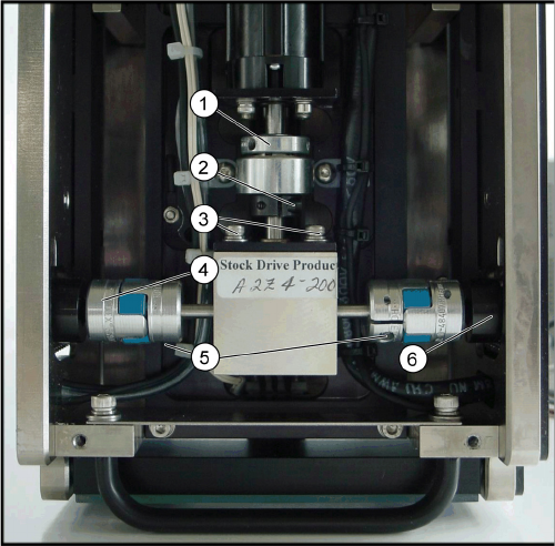
► (1) Check that the motor drive shaft coupling screws and both shaft collar screws are loose.
► See figure "Worm Gear Assembly".
► (2) Verify that the coupling is completely disconnected from the coupling adaptor (see figure "Worm
Gear Assembly").
► Verify that both of the elevator lift bars have full and equal freedom of motion (any signi fi cant drag
can result in gearbox failure).
This is a two-step process:
Worm Gear Assembly
1. Slip clutch
2. Motor drive shaft coupling screw use wrench: 3/32
hex key
3. Worm gear mounting screws use wrench: 7/64” hex
key driver
4. Coupling
5. Shaft collar screws use wrench: 3/32” hex key driver
6. Coupling adapter
Service Works
Service Base Unit 2.4.2 Worm Gear Drive Assembly Replacement Procedure
34 Service Manual SIPLACE JEDEC Tray Feeder
► To verify freedom of motion, move the elevator lift bar through its range of motion.
► Push the coupling and the shaft collar firmly into the coupling adaptor.
► Move the elevator lift bar through its range of motion.
► If any resistance or binding is felt, rotate the worm gearbox slightly to align the gearbox shaft with
the coupling.
► Loosen the shaft collar screw and repeat these steps for the other elevator lift bar assembly.
► (3) Verify that both shaft collar screws are loosened.
► Put the whole feeder upside-down.
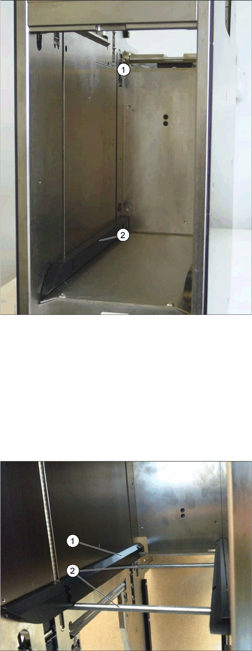
Checking the Elevator Lift Bars
1. Elevator bar range of motion
2. Elevator lift bar
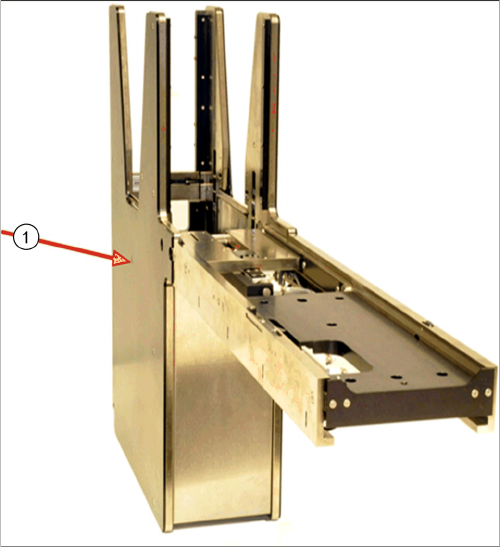
Rest the elevator lift bar against the two alignment pins
1. Elevator lift bar
2. Use alignment pins, part number 8045528
Service Works
2.4.3 Cleaning and Replacing Short Pawls (SIPLACE JTF-S) Service Base Unit
Service Manual SIPLACE JEDEC Tray Feeder 35
► Place the two dowel pins, provided in maintenance kit, into the holes in the left and the right side
plates as shown in fig." Rest the elevator lift bar against the two alignment pins" (If the pins are not
available use four 1⁄4 -20 socket head cap screws or 6mm socket head cap screws).
► Position the elevator lift bar so it rests firmly against the alignment pins.
► (4) While maintaining pressure on the elevator lift bar, tighten the left shaft collar screw while making
sure the coupling is extended all the way toward the outer walls.
► Repeat steps 3 and 4 to align the right elevator bar.
► (5) Tighten the worm gear mounting screws.
► (6) Tighten the motor drive shaft coupling screw.
► (7) Before turning on the power to the unit, check the assembly for freedom of movement by turning
the motor shaft by hand using the slip clutch assembly.
2.4.3
2.4.3 Cleaning and Replacing Short Pawls (SIPLACE JTF-S)
Cleaning and Replacing Short Pawls (SIPLACE JTF-S)
The following procedure outlines how to remove, clean and replace a short pawl from the pawl lift rod.
► Remove the side cover as shown in figure "Disconnecting Conveyor from Base".
► Remove the pawl lift rod as shown in figure "Disconnecting Conveyor from Base".
► Remove the short pawl by pushing the dowel pin out of the pawl lift rod as shown in figure "Removing
the Conveyor Rail".
► Clean the dowel pin and short pawl with alcohol. Be certain the pawl moves freely on the dowel pin
before assembling the pawl on the lift rod (see figure "Removing the Conveyor Rail").
► Replace the short pawl and reinstall the dowel pin.
► Be sure the dowel pin does not protrude from the pawl lift rod (see figure "Disconnecting Conveyor
from Base").
► Be sure the short pawl moves freely (see figure "Removing the Conveyor Rail").
► Reinstall the pawl lift rod and attach the side cover.
► Be certain the retracted short pawls on both lift rods move freely when installing the side cover (see
figure "Old Guide Blocks").
► Double check short pawl movement after mounting side panels.
Remove the side cover
1. Remove the side cover (twelve sunk screws).