00197543-01_SM_JTF-S_ JTF-M_en - 第45页
Service Works 2.5.6 Return Pusher Pneumatic Adjustment Setup and Adjustment Co nveyor Unit Service Manual SIPLACE JEDEC Tray Feeder 45 ► Decrease the "retur n to home position" speed by turning the adj ustment …
Service Works
Setup and Adjustment Conveyor Unit 2.5.6 Return Pusher Pneumatic Adjustment
44 Service Manual SIPLACE JEDEC Tray Feeder
► To increase the speed of the pushing function, turn adjustment screw B counter clock- wise.
► To decrease the speed of the pushing function, turn adjustment screw B clock- wise.
► Tighten locking nut B when adjustment is complete.
2.5.6
2.5.6 Return Pusher Pneumatic Adjustment
Return Pusher Pneumatic Adjustment
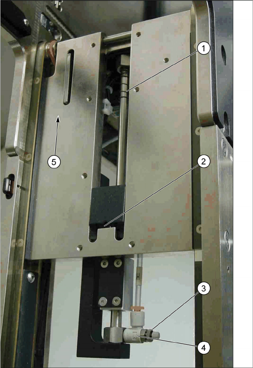
Two fl ow control valves control the speed of the return pusher function. The fl ow control at the end of the
return pusher assembly controls the "return to home" speed (see figure "Flow Control Locations - Return
Pusher").
The "forward push" fl ow control valve is located next to the control board under the front cover (see Fig.
"Flow Control Locations - Return Pusher"). The following procedure outlines adjustments for both func-
tions.
► Be certain the internal air pressure is 60 psi before making these fl ow control adjustments (see Sec-
tion "2.6.1 Main Air Regulator Adjustment" [ ➙ 47]).
► When adjusting the "forward push" speed, set the speed fast enough to overcome the slowdown
spring tension, but slow enough not to dislodge components from the trays, if the trays being re-
turned will not be empty.
► Adjust the "return to home position" speed so pusher returns to the home position without any hesi-
tation.
► To adjust the "return to home position" speed, unlock the adjustment screw by loosening the locking
nut (see figure "Flow Control Locations - Return Pusher").
► To increase the "return to home position" speed, turn the adjustment screw in a counter clockwise
direction.
Flow control locations - Return pusher
1. Slow down spring
2. Return“ pusher home position
3. Locking nut
4. „Return to home position“ flow control
5. Forward Push direction
Service Works
2.5.6 Return Pusher Pneumatic Adjustment Setup and Adjustment Conveyor Unit
Service Manual SIPLACE JEDEC Tray Feeder 45
► Decrease the "return to home position" speed by turning the adjustment screw in a clockwise direc-
tion.
► When the adjustment is correct, tighten the locking nut.
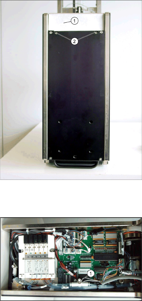
► To adjust the "forward push" speed, remove the front cover by loosening the two screws shown in
figure "Front Cover Screw Locations".
► Locate the "forward push" speed fl ow control valve (see figure "Forward Push Flow Control").
► Unlock the adjustment screw by loosening the locking nut (this is the same type of fl ow control valve
as shown in figure "Forward Push Flow Control").
► To increase the "forward push" speed, turn the adjustment screw in a counter clock wise direction.
► Decrease the "forward push" speed by turning the adjustment screw in a clockwise direction.
► When the adjustment is complete, tighten the locking nut.
► Reinstall the front cover.
Front cover screw locations
1. Front cover
2. Front cover screws The screws are recessed into bot-
tom cover.
Forward push flow control
1. Forward push speed flow control valve
Service Works
Setup and Adjustment Conveyor Unit 2.5.7 Lift Cylinder Flow Control Adjustments (SIPLACE JTF-S)
46 Service Manual SIPLACE JEDEC Tray Feeder
2.5.7
2.5.7 Lift Cylinder Flow Control Adjustments (SIPLACE JTF-S)
Lift Cylinder Flow Control Adjustments (SIPLACE JTF-S)
The speed settings for the lift cylinder must sometime be changed in relation to the weight of the stack
of trays. To maximize the throughput on the feeder, increase each fl ow control setting until you fi nd the
fastest speed at which the entire stack of trays cycles in a smooth motion without upsetting the compo-
nents in the trays.
► Before performing this adjustment, check that the input pressure to the feeder is 60 psi.
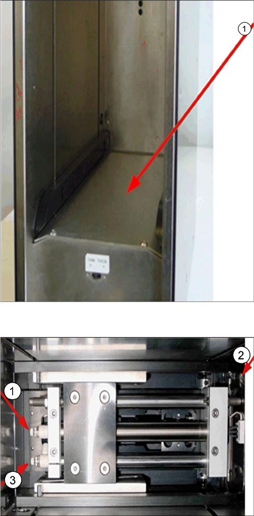
► Remove the lift cylinder cover (see figure "Removing Front Cover").
► Before making this adjustment, you must fi rst unlock the fl ow control by turning the locking knob
counter clockwise.
Lift cylinder cover
1. Lift cylinder cover
Lift cylinder flow controls
1. Lift cylinder down flow control
2. Loading door side
3. Lift cylinder up flow control