00197543-01_SM_JTF-S_ JTF-M_en - 第46页
Service Works Setup and Adjustment Conveyor Unit 2.5.7 Lift Cylinder Flow Cont ro l Adjustments (SIPLACE JTF-S ) 46 Service Manual SIPLACE JEDEC Tray Feeder 2.5.7 2 . 5 . 7 L if t C y lin d e r F lo w C o n t r o l A d j…
Service Works
2.5.6 Return Pusher Pneumatic Adjustment Setup and Adjustment Conveyor Unit
Service Manual SIPLACE JEDEC Tray Feeder 45
► Decrease the "return to home position" speed by turning the adjustment screw in a clockwise direc-
tion.
► When the adjustment is correct, tighten the locking nut.
► To adjust the "forward push" speed, remove the front cover by loosening the two screws shown in
figure "Front Cover Screw Locations".
► Locate the "forward push" speed fl ow control valve (see figure "Forward Push Flow Control").
► Unlock the adjustment screw by loosening the locking nut (this is the same type of fl ow control valve
as shown in figure "Forward Push Flow Control").
► To increase the "forward push" speed, turn the adjustment screw in a counter clock wise direction.
► Decrease the "forward push" speed by turning the adjustment screw in a clockwise direction.
► When the adjustment is complete, tighten the locking nut.
► Reinstall the front cover.
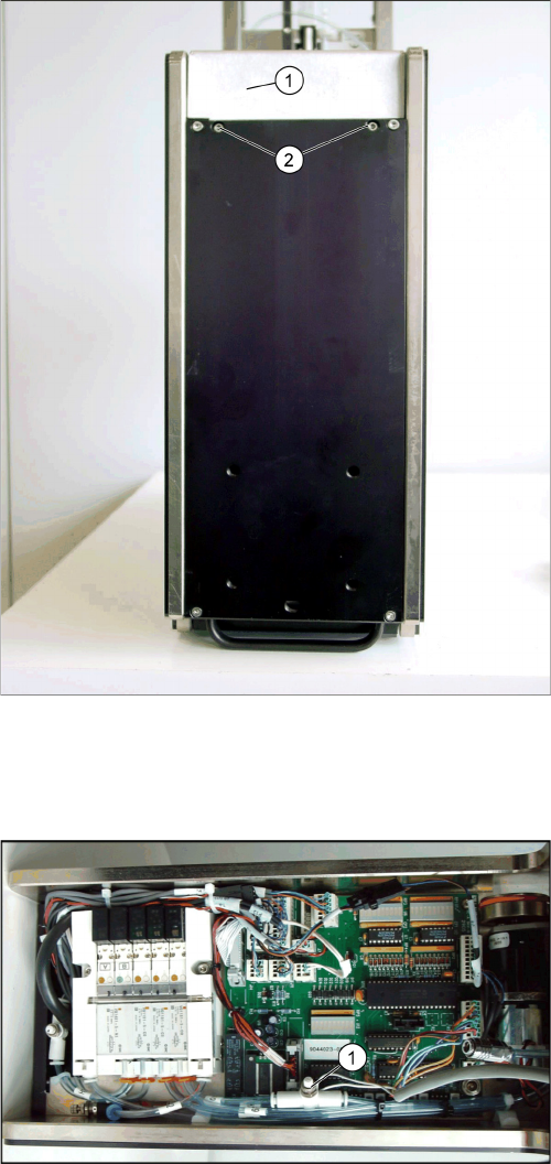
Front cover screw locations
1. Front cover
2. Front cover screws The screws are recessed into bot-
tom cover.
Forward push flow control
1. Forward push speed flow control valve
Service Works
Setup and Adjustment Conveyor Unit 2.5.7 Lift Cylinder Flow Control Adjustments (SIPLACE JTF-S)
46 Service Manual SIPLACE JEDEC Tray Feeder
2.5.7
2.5.7 Lift Cylinder Flow Control Adjustments (SIPLACE JTF-S)
Lift Cylinder Flow Control Adjustments (SIPLACE JTF-S)
The speed settings for the lift cylinder must sometime be changed in relation to the weight of the stack
of trays. To maximize the throughput on the feeder, increase each fl ow control setting until you fi nd the
fastest speed at which the entire stack of trays cycles in a smooth motion without upsetting the compo-
nents in the trays.
► Before performing this adjustment, check that the input pressure to the feeder is 60 psi.
► Remove the lift cylinder cover (see figure "Removing Front Cover").
► Before making this adjustment, you must fi rst unlock the fl ow control by turning the locking knob
counter clockwise.
Lift cylinder cover
1. Lift cylinder cover
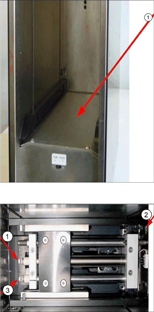
Lift cylinder flow controls
1. Lift cylinder down flow control
2. Loading door side
3. Lift cylinder up flow control
Service Works
2.6.1 Main Air Regulator Adjustment Setup and Adjustments Base Unit
Service Manual SIPLACE JEDEC Tray Feeder 47
► To increase the airflow and increase the speed of the tray stack lift, turn the flow control adjustment
knob in a counter clockwise direction.
► To decrease the airflow and decrease the speed of the tray stack lift, turn the flow control adjustment
knob in a clockwise direction.
► When you are satis fi ed with the lift cylinder adjustments, lock the fl ow controls and assemble the lift
cylinder cover.
2.6
2.6 Setup and Adjustments Base Unit
Setup and Adjustments Base Unit
2.6.1
2.6.1 Main Air Regulator Adjustment
Main Air Regulator Adjustment
► (1) Check the air pressure reaching the feeder. This should be 60 psi (4.1 bars).
Newer feeders which are prepared to work with the air pressure gauge (air pressure maintenance kit -
P/N 9043931). This kit allows you to check the pressure actually reaching the feeder. Connect the pres-
sure gauge to the micro coupler (see figure "Air pressure gauge from maintenance kit") and check that
the output pressure is 60 psi (4.1 bars). If adjustment is required, remove the front cover (step 2), then
perform steps 7, 8, 9 and 11. On older feeders it is necessary to disconnect air pressure to the feeder
and follow steps 2 thru 6. If adjustment is required follow steps 7 through 11.
► (2) Remove the front cover by loosening the two M4 screws (see figure "Remove Front Cover" for
screw locations).
► (3) After removing the front cover, locate the main air pressure regulator (see figure" Location of
Pressure Regulator").
► (4) Disconnect the output line tubing line H2. See figure "Location of Pressure Regulator".
► (5) Connect the air pressure gauge to the output line (see figure "Checking The Main Air Pressure").
► (6) Reconnect the air pressure to the feeder.
⇨ The air pressure coming from the pressure regulator should be 60 psi (4.1 bars).
► (7) If the output air pressure must be adjusted, unlock the regulator adjustment screw by loosening
the locking knob (see figure "Location of Pressure Regulator").
► (8) To increase the output air pressure, turn the adjustment screw counter clock wise (see figure "Lo-
cation of Pressure Regulator"). To decrease the output air pressure, turn the adjustment screw
clockwise.
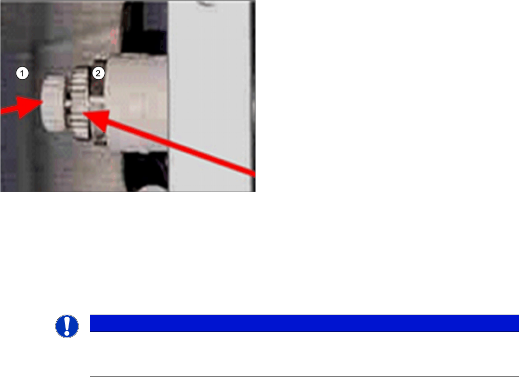
Flow control locations – Lift cylinders
1. Flow control adjustment knob
2. Flow control locking knob
NOTICE
The flow control adjustment knob
When locking a flow control, be certain the flow control adjustment knob does not move when
you are turning the flow control locking knob.