00197543-01_SM_JTF-S_ JTF-M_en - 第59页
Service Works 2.6.6 Lift Cylinder Shock Absorber Adjustment SIPLACE JTF-S Setu p and Adjustments Base Unit Service Manual SIPLACE JEDEC Tray Feeder 59 Lift mechanism cover 1. Lift m echanism cover Shock absorber adju stm…
Service Works
Setup and Adjustments Base Unit 2.6.5 Checking Pawl Movement (SIPLACE JTF-S)
58 Service Manual SIPLACE JEDEC Tray Feeder
2.6.5
2.6.5 Checking Pawl Movement (SIPLACE JTF-S)
Checking Pawl Movement (SIPLACE JTF-S)
Both the short pawls and long pawls are located in the tower area of the feeder, near the level of the
conveyor (see figure "Bottom Plate and Mounting Screws"). If the pawls do not move freely, the motion
of the trays may become unreliable.
► To test a short pawl, move each one with your fi nger. Each short pawl should move easily.
► To test a long pawl, push the long pawl to one side.
► Check to see that the long pawl can move freely in the up-and-down direction.
► Push the long pawl to the other side, and test again.
If the pawls are sticking, do not lubricate them! The lubrication will cause the pawls to stick, and increase
the problem. Instead, disassemble the mechanism and clean the parts using alcohol.
2.6.6
2.6.6 Lift Cylinder Shock Absorber Adjustment SIPLACE JTF-S
Lift Cylinder Shock Absorber Adjustment SIPLACE JTF-S
The lift cylinder shock absorbers are designed to slow the rod less cylinder body at the end of its stroke
(see figure "Slip clutch elevator"). The shock absorber is not designed to be used as a stop. The rod less
cylinder body stop point is determined by the pawl lift rod stopping at its end of travel.
The following procedure outlines how to verify the shock absorbers are correctly adjusted, and how to
adjust if necessary.
► Remove the cover on the lift mechanism (see figure "Alignment Pins").
► Disconnect power to the feeder (leave the air pressure connected).
► Manually fi re the lift cylinder down and measure the gap between the lift cylinder body and the shock
absorber (see figure "Incorrect-Elevator Bar is Not Level" to locate the lift cylinder manual activation
solenoid valves).
⇨ The gap should be approx. 3/32." (see figure Incorrect – Elevator Bars at same Level"). The body of
the shock absorber must not contact the body of the lift cylinder.
► Manually fi re the lift cylinder up and observe the gap between the lift cylinder body and the shock
absorber on the other end of the stroke. The gap should be approx. 3/32."
► If adjustment is required, loosen the lock nut on the shock absorber and turn the shock absorber until
the proper gap is reached.
► Tighten the lock nut.
► Manually fi re the lift cylinder in the opposite direction then back again to verify proper adjustment.
► Attach the lift mechanism cover.
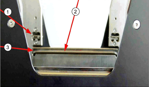
Checking pawl movement
1. Short pawl
2. The long pawl should be able to move up and down
freely
3. Long pawl
Service Works
2.6.6 Lift Cylinder Shock Absorber Adjustment SIPLACE JTF-S Setup and Adjustments Base Unit
Service Manual SIPLACE JEDEC Tray Feeder 59
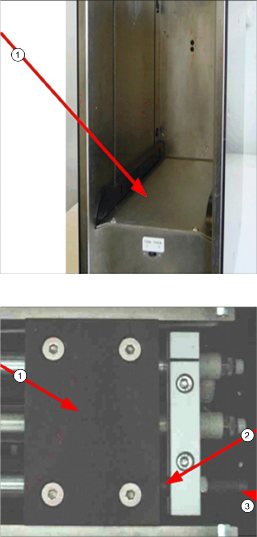
Lift mechanism cover
1. Lift mechanism cover
Shock absorber adjustment
1. Lift cylinder body
2. Shock absorber and lift cylinder body gap setting
3. Shock absorber
Service Works
Setup and Adjustments Base Unit 2.6.6 Lift Cylinder Shock Absorber Adjustment SIPLACE JTF-S
60 Service Manual SIPLACE JEDEC Tray Feeder
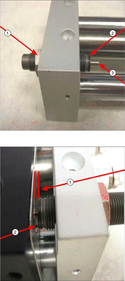
Details of shock absorber
1. Shock absorber lock nut
2. Shock absorber body
3. Shock absorber plunger
Shock absorber gap setting
► Do not allow the lift cylinder body to touch the shock
absorber body (2).
► Set gap (1) to approx. 3/32”.