00197543-01_SM_JTF-S_ JTF-M_en - 第64页
Service Works Troubleshooting SIPLACE JTF-M 2.7 .4 Troubleshooting Charts SIPLA CE JTF-M 64 Service Manual SIPLACE JEDEC Tray Feeder 2. Tray clamp tube H9 3. Out feed pushe r tube H7 and H8 2.7.4 2 . 7 . 4 T r o u b le s…
Service Works
2.7.2 Input and Sensor Status on Control Board (SIPLACE JTF-M) Troubleshooting SIPLACE JTF-M
Service Manual SIPLACE JEDEC Tray Feeder 63
2.7.2
2.7.2 Input and Sensor Status on Control Board (SIPLACE JTF-M)
Input and Sensor Status on Control Board (SIPLACE JTF-M)
This is a list of the functions indicated by the LEDs input banks U1 and U6:
These LED status can be very helpful when trouble shoot any sensor or communication issues.
2.7.3
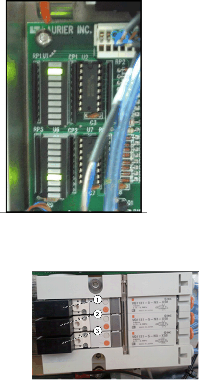
2.7.3 Checking the Indicator LEDs on the Solenoid Bank (SIPLACE JTF-M)
Checking the Indicator LEDs on the Solenoid Bank (SIPLACE JTF-M)
The feeder includes a bank of at least fi ve solenoids that control the pneumatic functions. Each solenoid
includes an LED that lights when that solenoid is active. These can also be helpful as you troubleshoot
the feeder.
Indicator LEDs on Solenoids and pneumatic tube connection
1. Tray return pusher tube H10 and H11
Location Function:
▪ U1-3 - Forward slow sensor
▪ U1-4 - Stop at end sensor
▪ U1-5 - Slot sensor
▪ U1-6 - Reset button
▪ U1-7 - Stop button
▪ U1-8 - Spare
▪ U6-1 - Inhibit button
▪ U6-2 - Elevator down button
▪ U6-4 - Tray in magazine sensor
▪ U6-5 - Reverse slow sensor
▪ U6-6 - Elevator high sensor
▪ U6-7 - Elevator low sensor
▪ U6-8 - Door sensor
▪ U6-9 - Manual index Buttons (2)

Service Works
Troubleshooting SIPLACE JTF-M 2.7.4 Troubleshooting Charts SIPLACE JTF-M
64 Service Manual SIPLACE JEDEC Tray Feeder
2. Tray clamp tube H9
3. Out feed pusher tube H7 and H8
2.7.4
2.7.4 Troubleshooting Charts SIPLACE JTF-M
Troubleshooting Charts SIPLACE JTF-M
2.7.4.1
2.7.4.1 General Issues
General Issues
Problem Possible Cause Solution
On power-up, the feeder will not
operate. There are no lights on
the panels or sensors at all.
The feeder may not be getting
power.
► Make sure the feeder is
plugged into the assembly
machine.
The feeder powers up, but does
not operate.
The Stop button on the feeder
may have been hit (Stop LED lit).
► If the host machine is not pro-
viding power to J2 pins 1
(+24V) and 2 (common), un-
plug the cable and check for
24V DC on pins 1 and 2.
The host machine may not be
supplying enough compressed
air (Stop LED is flashing).
► Make sure the host machine
is on and not in an E-Stop
condition.
All of the pneumatic functions
seem slow or sluggish.
The host machine may not be
supplying enough compressed
air.
► Check the voltage reaching
the feeder.
The main air regulator in the
feeder may be set up incorrectly.
► Press the Reset button.
One pneumatic function is slow
or sluggish.
The mechanism may be blocked
or jammed.
► Make sure that the feeder air
feed line is connected to the
assembly machine.
The flow control(s) for that func-
tion may need adjustment.
► Make sure that the air supply
on the assembly machine is
on.
The valve block for that function
may be bad.
► Make sure the assembly ma-
chine is supplying at least 60
psi or 4 Bar.
The cylinder for that function may
be bad.
► Make sure the host machine
is supplying at least 60 psi or
4 Bar.
All of the pneumatic functions
seem too fast.
The air pressure from the host
machine may be too high.
► Make sure that the air feed
line is not pinched.
The main air regulator on the
feeder may be set up incorrectly.
► Check for variations in air
supply from the host ma-
chine.
One pneumatic function is too
fast.
The flow control(s) for that func-
tion may need adjustment.
► Set this to provide 60 psi.

Service Works
2.7.4 Troubleshooting Charts SIPLACE JTF-M Troubleshooting SIPLACE JTF-M
Service Manual SIPLACE JEDEC Tray Feeder 65
2.7.4.2
2.7.4.2 Logic and Communication Problems
Logic and Communication Problems
Problem Failure Symptom Failure Solution
Error on feeder (blinking
orange LED), error sig-
nal sent to host ma-
chine.
STOP_ERROR Stop button pushed.
Stop button stuck or
faulty.
► Press Reset Button
to continue.
► Check U1-7 status
and switch.
FAILED_TO_RECLAMP Re-Clamp of the tray in
the Ready position failed
during initialization or re-
set.
► Press Reset to con-
tinue.
TRAY_IN_MAGAZINE Tray exchange initiated
with tray partially in
magazine.
► Remove tray from
“tray in magazine”
sensor.
► Press Reset to con-
tinue.
LIFT NOT DOWN
ELEV_NOT_IN_POSITI
ON
The tray elevator did not
go down all of the way.
► See "2.7.4.3 Eleva-
tor and Tray Ex-
change Problems"
[ ➙ 66]“Elevator will
Not Go Down.”
TRAY_NOT_CLEAR The tray returning from
the pick position did not
clear the “return slow-
down” sensor.
► See "2.7.4.4 Con-
veyor and Sensor
Problems Tray feed
Cycle"
[ ➙ 66]“Conveyor
and Sensor Prob-
lems.
TRAY_NOT_IN The tray returning from
the pick position did not
reach the “stop at stack”
sensor.
► See "2.7.4.4 Con-
veyor and Sensor
Problems Tray feed
Cycle"
[ ➙ 66]“Conveyor
and Sensor Prob-
lems – Return
Cycle.”
TRAY_NOT_FED The tray returning from
the pick position did not
reach the “stop at stack”
sensor.
► See "2.7.4.4 Con-
veyor and Sensor
Problems Tray feed
Cycle"
[ ➙ 66]“Conveyor
and Sensor Prob-
lems – Return
Cycle.”
TRAY_NOT_AT_END The tray being conveyed
to the pick position did
not reach the “forward
slow-down” sensor be-
fore timeout.
► See "2.7.4.3 Eleva-
tor and Tray Ex-
change Problems"
[➙66]“Elevator and
Tray Exchange
Problems.”