yg200BLOW_kgt_e
YG200 KGT 0612 Contr ol Wiring Diagram

YG200
KGT 0612
Control Wiring Diagram
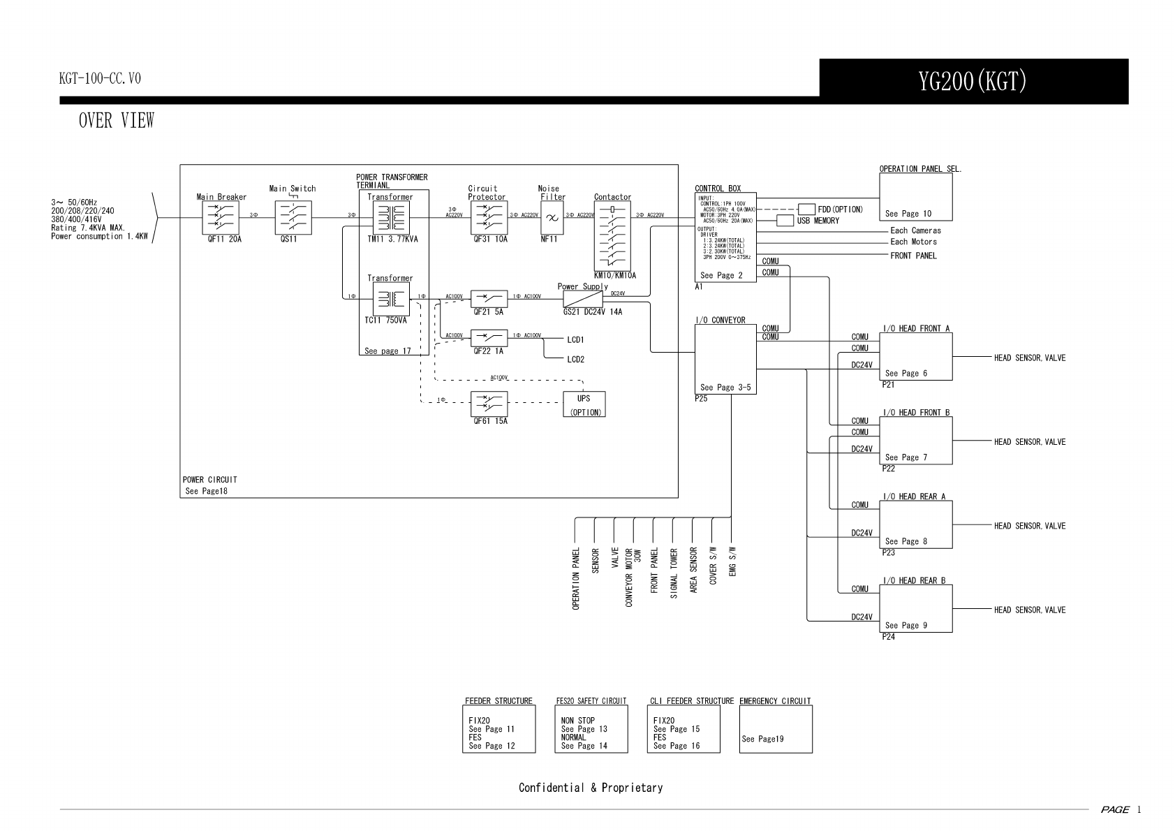
YG200(KGT)
Over view
Control box
I/O conveyor board -1-
I/O conveyor board -2-
I/O conveyor board -3-
I/O head front A (HEAD A)
I/O head front B (HEAD B)
I/O head rear A (HEAD C)
I/O head rear B (HEAD D)
Operation panel sel.
FIX20 feeder structure
FES20 feeder structure
FES20 safety circuit (non stop)
FES20 safety circuit (normal)
CLI FIX20 feeder structure
CLI FES20 feeder structure
Power transformer terminal
Power circuit
Emergency circuit
Air circuit (YG200-FNC)
Air circuit (YG200-FNC+FES)
Air circuit (YG200-SF)
Air circuit (YG200-SF+FES)
Wiring parts list
Table of contents
P. 1
P. 2
P. 3
P. 4
P. 5
P. 6
P. 7
P. 8
P. 9
P.10
P.11
P.12
P.13
P.14
P.15
P.16
P.17
P.18
P.19
P.20
P.21
P.22
P.23
P.24