Specification SIPLACE CA-Series2011版 - 第13页
13 Placement Heads Placement Head Configuration Description SIPLACE CA machines are characterize d by their e xcel- lent flexibility in the produc- tion process. This flexibility is partly due to the large selec- tion of…
12
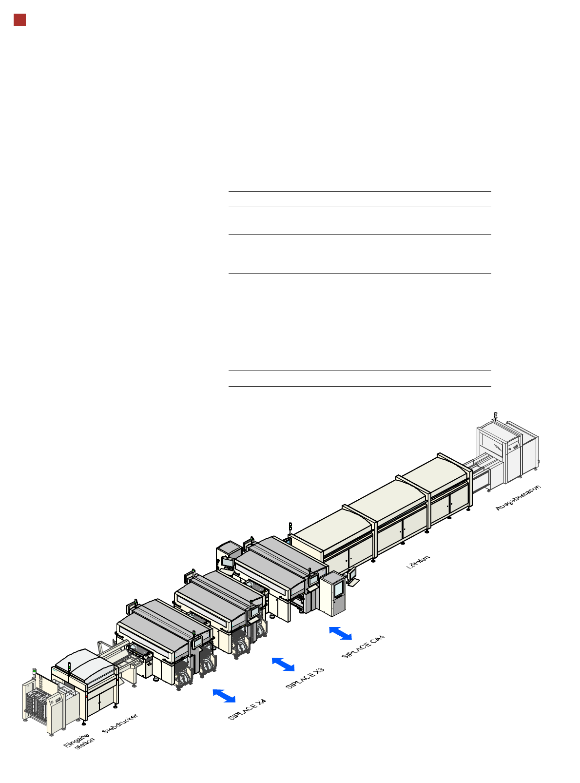
Line Concept
Description
Flexibility, modularity, com-
pact dimensions and high
power density are the hall-
marks of the new SIPLACE
concept. It allows a produc-
tion line to be individually
configured from identical and
different modules. If the pro-
duction requirements
change, the individual place-
ment machines are so com-
pact that they can be recom-
bined quickly and easily.
Operated together with the
SIPLACE X series, the
SIPLACE CA machine al-
lows you to individually con-
figure your production line
with both identical and differ-
ing modules. If the produc-
tion requirements change,
the individual placement ma-
chines are so compact and
can be combined with such
flexibility that they can be re-
combined quickly and easily.
The SIPLACE CA family has
the optimum placement sys-
tem for each individual per-
formance requirement.
System SIPLACE Placement lines
Placement
module
SIPLACE CA4/CA3, SIPLACE X series,
SIPLACE SX1/SX2,SX4
Peripheral
modules
Input/output stations, screen printer, sol-
dering furnace, inspection places etc.
available from SIPLACE
PCB conveyor Single and dual conveyor with auto-
matic width adjustment unit;
Dual conveyor in single conveyor mode
"Wide board" mode with "long board"
option and a combination of these for
both PCB conveyors. The maximum
PCB width is determined by the module
with the smallest PCB conveyor width.
Space required 6.7 m² per CA4 module
13
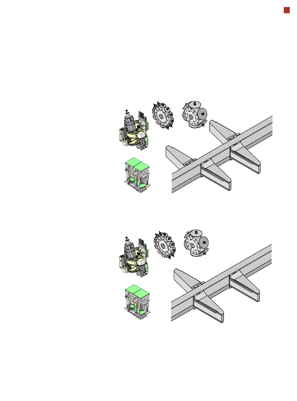
Placement Heads
Placement Head Configuration
Description
SIPLACE CA machines are
characterized by their excel-
lent flexibility in the produc-
tion process. This flexibility is
partly due to the large selec-
tion of placement head con-
figurations. Different
placement head variants can
be configured to suit individ-
ual production requirements.
The illustrations show the
placement head variants for
the SIPLACE CA3 and CA4
machines.
For a list of the available
placement head configura-
tions, refer to section
„Machine Performance“ from
page 10.
C&P12CA
C&P6CA
G1
G2
G3
G4
C&P20CA/C&P12CA/
C&P6CA/TH
C&P20CA/C&P12CA/
C&P6CA/TH
C&P20CA/C&P12CA/
C&P6/TH
C&P20CA/
C&P12CA/
C&P6CA/TH
C&P20CA
TH
Placement
area 2
SIPLACE CA4
Placement
area 1
Placement
area 2
Placement
area 1
SIPLACE CA3
TH
C&P12CA
G1
G3
G4
C&P20CA/C&P12CA/
C&P6CA/TH
C&P20CA/C&P12CA/
C&P6CA/TH
C&P20CA/C&P12CA/
C&P6CA/TH
C&P6CA
C&P20CA

14
Placement heads
Placement configuration
Placement area 1 Placement area 2
Gantry 1 Gantry 4 Gantry 2 Gantry 3
C&P20CA C&P20CA C&P20CA C&P20CA
C&P20CA C&P20CA C&P12 C&P12
C&P20CA C&P20CA C&P12 C&P6
C&P20CA C&P20CA C&P12 TH
a
C&P20CA C&P20CA C&P6 C&P6
C&P20CA C&P20CA C&P6 TH
a
C&P20CA C&P20CA TH
a
TH
a
C&P12 C&P12 C&P12 C&P12
C&P12 C&P12 C&P12 C&P6
C&P12 C&P12 C&P12 TH
a
C&P12 C&P12 C&P6 C&P6
C&P12 C&P12 C&P6 TH
a
C&P12 C&P12 TH
a
TH
a
C&P12 C&P6 C&P12 C&P6
C&P12C&P6C&P12 TH
a
C&P12 C&P6 C&P6 C&P6
C&P12 C&P6 C&P6 TH
a
C&P12 C&P6 TH
a
TH
a
C&P12 TH
a
C&P12 TH
a
C&P12 TH
a
C&P6 TH
a
C&P12 TH
a
TH
a
TH
a
C&P6 C&P6 C&P6 C&P6
C&P6 C&P6 C&P6 TH
a
C&P6 C&P6 TH
a
TH
a
C&P6 TH
a
C&P6 TH
a
C&P6 TH
a
TH
a
TH
a
TH
a
TH
a
TH
a
TH
a
a) A TwinHead can only be used in a placement area without SWS.
Placement head combination options for CA4