Specification SIPLACE CA-Series2011版 - 第15页
15 Placement heads Placement configuration Placement head combination options for CA3 Placement area 1 Placement area 2 Gantry 1 Gantry 4 Gantry 3 C&P20CA C&P20CA C&P12 C&P20CA C&P20CA C&P6 C&…

14
Placement heads
Placement configuration
Placement area 1 Placement area 2
Gantry 1 Gantry 4 Gantry 2 Gantry 3
C&P20CA C&P20CA C&P20CA C&P20CA
C&P20CA C&P20CA C&P12 C&P12
C&P20CA C&P20CA C&P12 C&P6
C&P20CA C&P20CA C&P12 TH
a
C&P20CA C&P20CA C&P6 C&P6
C&P20CA C&P20CA C&P6 TH
a
C&P20CA C&P20CA TH
a
TH
a
C&P12 C&P12 C&P12 C&P12
C&P12 C&P12 C&P12 C&P6
C&P12 C&P12 C&P12 TH
a
C&P12 C&P12 C&P6 C&P6
C&P12 C&P12 C&P6 TH
a
C&P12 C&P12 TH
a
TH
a
C&P12 C&P6 C&P12 C&P6
C&P12C&P6C&P12 TH
a
C&P12 C&P6 C&P6 C&P6
C&P12 C&P6 C&P6 TH
a
C&P12 C&P6 TH
a
TH
a
C&P12 TH
a
C&P12 TH
a
C&P12 TH
a
C&P6 TH
a
C&P12 TH
a
TH
a
TH
a
C&P6 C&P6 C&P6 C&P6
C&P6 C&P6 C&P6 TH
a
C&P6 C&P6 TH
a
TH
a
C&P6 TH
a
C&P6 TH
a
C&P6 TH
a
TH
a
TH
a
TH
a
TH
a
TH
a
TH
a
a) A TwinHead can only be used in a placement area without SWS.
Placement head combination options for CA4

15
Placement heads
Placement configuration
Placement head combination options for CA3
Placement area 1 Placement area 2
Gantry 1 Gantry 4 Gantry 3
C&P20CA C&P20CA C&P12
C&P20CA C&P20CA C&P6
C&P20CA C&P20CA TH
a
a) A TwinHead can only be used in a placement area without SWS.
C&P12 C&P12 C&P12
C&P12 C&P12 C&P6
C&P12 C&P12 TH
C&P12 C&P6 C&P12
C&P12 C&P6 C&P6
C&P12 C&P6 TH
a
C&P6 C&P6 C&P12
C&P6 C&P6 C&P6
C&P6 C&P6 TH
a
a) A TwinHead can only be used in a placement area without SWS.
b) C&P6 with SWS on request
16
Placement heads
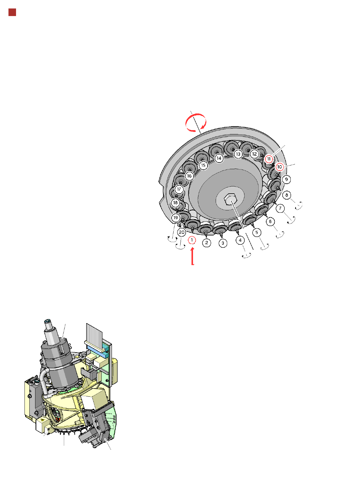
20 Segment Collect&Place CA
Head for Very High Speed Placement
Description
The 20 segment Collect&
-Place head operates ac-
cording to the Collect&Place
principle i.e. twenty compo-
nents are picked up from the
placement head within a sin-
gle cycle, are optically cen-
tered on the way to the board
and are also rotated into the
required placement position.
Lastly, the component is set
down gently and accurately
on the board.
The 20 segment -Col-
lect&Place head enables you
to significantly increase the
performance of the place-
ment head and the whole
placement machine. With the
help of high-resolution com-
ponent cameras, the 20 seg-
ment Collect&Place head
can optically center and
place components of size
01005, up to 6 mm x 6 mm.
Checking and self-learning
functions
Various control and self-
learning functions enhance
the reliability of the Col-
lect&Place head.
• To increase placement ac-
curacy, the 20 segment
Collect&Place head fea-
tures a component sen-
sor. At the pickup and
placement position, it
checks that the compo-
nent is present at the noz-
zle. The sensor only
supports components up
to a thickness of 90µm.
• The digital component
camera on the placement
head determines the
package form and the pre-
cise position of each com-
ponent at the nozzle.
Deviations from the pickup
position are corrected be-
fore placement.
• A sensor registers the rel-
ative movement between
the nozzle and the seg-
ment when components
are placed and sends a
signal to the position con-
trol axes.
With this sensor stop
method, differences in
height during pickup and
any unevenness of the
PCB surface are compen-
sated during placement.
Star
rotation
Pick up compo-
nent and place it
Turn component
individually
Optically center
component
Check
vacuum
Component
sensor
Component
sensor
Star motor
Star with 20 nozzles Component
camera