Specification SIPLACE CA-Series2011版 - 第19页
19 Placement heads Technical Data for C&P Heads 20 segment Collect&Place CA head component came ra type 41 12 segment Collect&Place CA head component camera type 29 6 segment Collect&Place CA head compone…
18
Placement heads
6 Segment Collect&Place CA
Head for High Speed IC Placement
Description
The 6 segment
Collect&Place head also
operates according to the
Collect&Place principle. With
the help of a high-resolution,
digital component camera,
the 6 segment Collect&Place
head can optically center and
place components of size
0201, up to 27 mm x 27 mm.
Checking and self-learning
functions
The control and self-learning
functions, described on page
17 for the 12 segment
Collect&Place head, also
apply to the 6 segment Col-
lect& Place head.
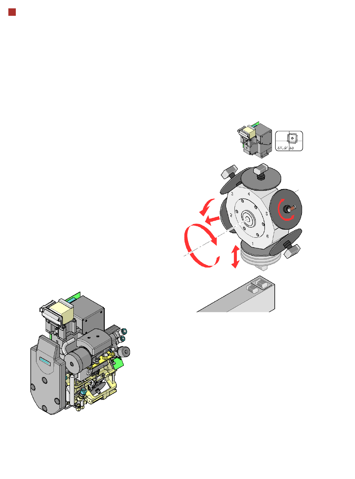
Component vision module
DP axis:
Rotate component
into placement posi-
tion
Z axis:
Pick up component or place it
DR axis:
Star rotation
Reject component,
pull off or
insert sleeve
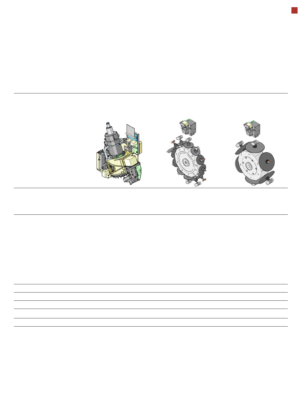
19
Placement heads
Technical Data for C&P Heads
20 segment
Collect&Place CA head
component camera type 41
12 segment
Collect&Place CA head
component camera type 29
6 segment
Collect&Place CA head
component camera type 29
Component range
a
a) Please note that the range of components that can be placed is also affected by the pad geometry, customer-specific standards,
component packaging tolerances and component tolerances.
01005 to 2220, Melf, SOT,
SOD, Bare-Die, Flip-Chip
0201
b
to Flip-Chip, Bare-
Die, PLCC44, BGA, µBGA,
TSOP, QFP, SO to SO32,
DRAM
b) with 0201 package;
0201 to 27 mm x 27 mm
Component spec.
max. height
min. lead pitch
min. lead width
min. ball pitch
min. ball diameter
min. dimensions
max. dimensions
max. weight
4 mm
0.08 mm
0.03 mm
0.10 mm
0.05 mm
0.12 mm x 0.12 mm
6 mm x 6 mm
1 g
6 mm
0.3 mm
0.15 mm
0.13 mm
0.08 mm
0.6 mm x 0.3 mm
18,7 mm x 18,7 mm
2 g
8.5 mm
0.3 mm
0.15 mm
0.13 mm
c
0.35 mm
d
0.08 mm
c
0.2 mm
d
0.6 mm x 0.3 mm
27 mm x 27 mm
5 g
c) for components < 18 mm x 18 mm;
d) for components 18 mm x 18 mm.
Programmable set-down force 1.5 N - 4.5 N 2.4 N - 5.0 N 2.4 N - 5.0 N
Nozzle types 10xx, 11xx, 12xx 9 xx 8 xx, 9 xx
X/Y accuracy (SMT) ± 41 µm/3 ± 41 µm/3 ± 45 µm/3
X/Y accuracy (CA)
e
e) Calculated with glass die on glass plate - SIPLACE MAC test
± 10 µm/3 ± 25 µm/3 ± 35 µm/3
Angular accuracy ± 0.5° / 3 ± 0.5° / 3 ± 0.2° / 3
20
Placement heads
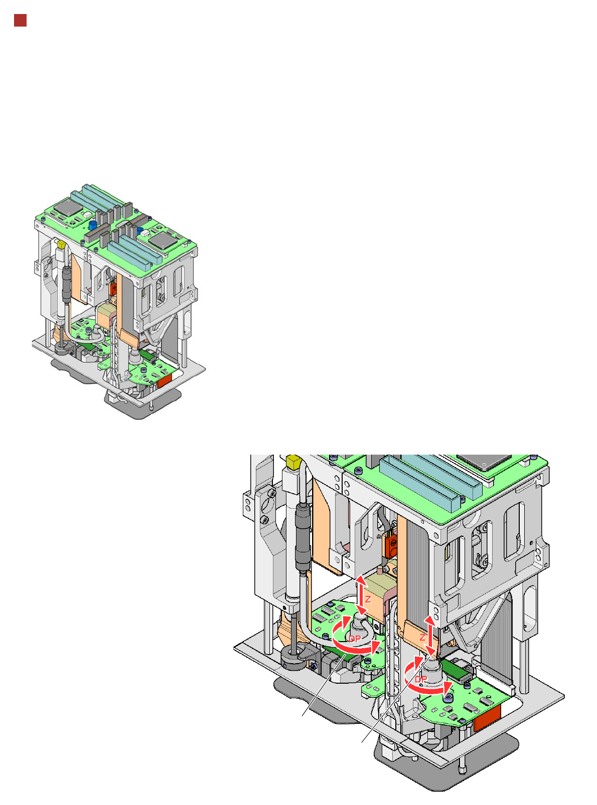
TwinHead for High-Precision IC Placement
Description
This sophisticated placement
head consists of two place-
ment heads of the same type
coupled together -(twin
head). Both heads work
using the Pick&Place prin-
ciple. The TwinHead is suit-
able for processing
particularly difficult or large
components. Two compo-
nents are picked up by the
placement head, optically
centered on the way to the
placement position and
rotated into the necessary
placement angle. They are
then set down gently and
accurately on the board.
In addition to the new noz-
zles recently developed for
the Twin Head, the place-
ment head can also use the
nozzles for the Pick&Place
head - used on the F5 HM.
Collect& Place head nozzles
can also be used.
Checking and self-learning
functions
The TwinHead's reliability
can be further increased with
various checking and self-
learning functions.
• For example, vacuum
checks at the nozzles indi-
cate whether the compo-
nent was picked up or set
down correctly.
• High-resolution, digital
component vision camer-
as such as the fine-pitch
and flip-chip vision camer-
as (optional) identify the
smallest deviations in the
component position. The
digital vision system cor-
rects such deviations, thus
guaranteeing a correct
placement position. The
digital component camer-
as are permanently fixed
to the machine frame.
• The component package
form is also checked, and
the component is not
placed if the geometric
data thus determined dif-
fers from the programmed
data.
• A force sensor measures
and monitors the specified
component placement
forces.
Z axis
DP axis
How the TwinHead works