Specification SIPLACE CA-Series2011版 - 第30页
30 PCB Conveyor Flexible Dual Conveyor Technical Data for the Dual Conveyor S tationary conveyor side Right or lef t PCB format S tandard (len gth x wid th) Wide board configuration Long boar d option Long board option a…
29
PCB Conveyor
Flexible Dual Conveyor
Description
As a result of reduced sec-
ondary processing times and
in conjunction with the opti-
mum placement program,
the PCB dual conveyor can
significantly enhance
throughput times. It allows
two PCBs to be carried si-
multaneously (synchronous-
ly) or alternately
(asynchronously) through
the placement machine.
In asynchronous mode, only
one PCB is processed in
each conveyor lane. At the
same time, another PCB in
the second conveyor lane is
moved into the placement
position. This saves the full
conveying time of one PCB,
thus considerably increasing
performance, particularly for
PCBs with a short cycle time.
The placement process
starts as soon as one PCB is
transported into the process-
ing area.
In synchronous mode-, two
PCBs are moved into the
placement position at the
same time. They are pro-
cessed as a common panel.
This facilitates the process-
ing of a board upper and un-
derside in one line. The
amount of nonproductive
secondary processing time is
reduced, as two boards are
always transported at the
same time.
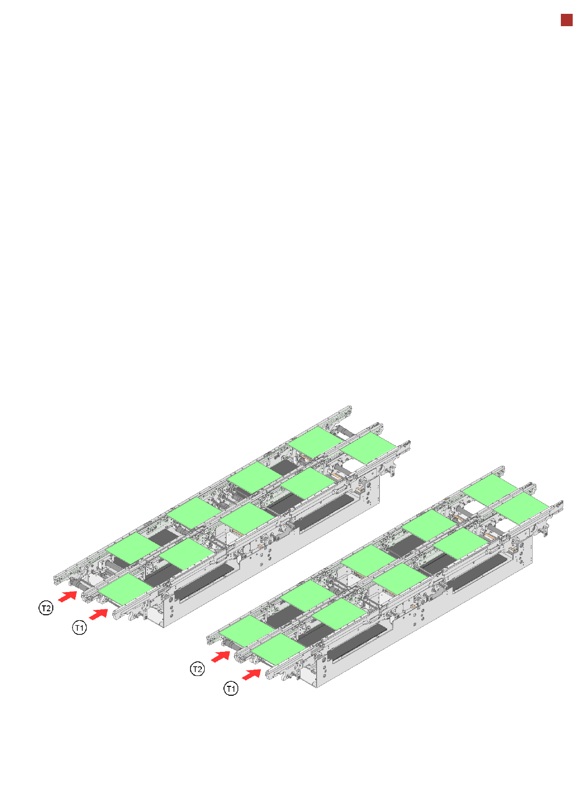
Asynchronous conveyor mode
Synchronous conveyor mode
30
PCB Conveyor
Flexible Dual Conveyor
Technical Data for the Dual Conveyor
Stationary conveyor side Right or left
PCB format
Standard (length x width)
Wide board configuration
Long board option
Long board option and Wide board
configuration
Dual conveyor in Single conveyor mode
Standard
Wide board configuration
Long board option
Long board option and Wide board
configuration
50 mm x 50 mm to 450 mm x 216 mm
50 mm x 50 mm to 450 mm x 250 mm
50 mm x 80 mm to 610 mm x 216 mm
50 mm x 80 mm to 610 mm x 250 mm
50 mm x 50 mm to 450 mm x 380 mm
50 mm x 50 mm to 450 mm x 450 mm
50 mm x 80 mm to 610 mm x 380 mm
50 mm x 80 mm to 610 mm x 450 mm
PCB thickness
Standard
0.3 mm to 4.5 mm (± 0.2 mm)
(standard, thicker PCBs on request)
Vacuum tooling on request
Thin PCBs on a carrier
Board warpage see page 31
PCB weight max. 3 kg
Clearance on PCB underside
Standard
Option
25 mm ± 0.2 mm
max. 40 mm ± 0.2 mm
PCB transport height 830mm ± 15mm (standard)
900mm ± 15mm (optional)
930mm ± 15mm (optional)
950mm ± 15mm (SMEMA: optional)
Type of interface SMEMA / Siemens
Component-free PCB handling edge 3 mm
PCB changeover time < 2.5 s
PCB positioning accuracy ± 0.5 mm
Conveyor mode synchronous or asynchronous
Components on each conveyor same or different
PCB width on each conveyor same or different
Inkspot detection on the PCB synchronous: possible (no global inkspot)
asynchronous: possible
Automatic width adjustment synchronous: possible, asynchronous:
possible
31
PCB Conveyor
Board Warpage
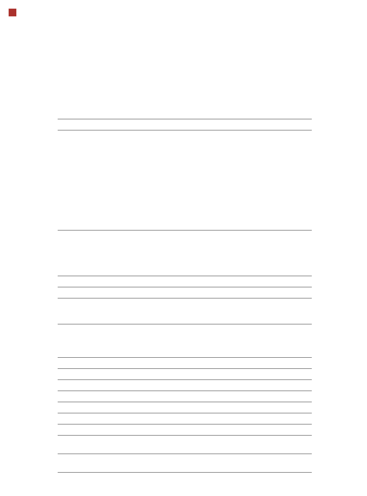
PCB warpage across the direction of travel
max. 1 % of the PCB diagonal, but not ex-
ceeding 0.5 mm
PCB warpage on the conveyor
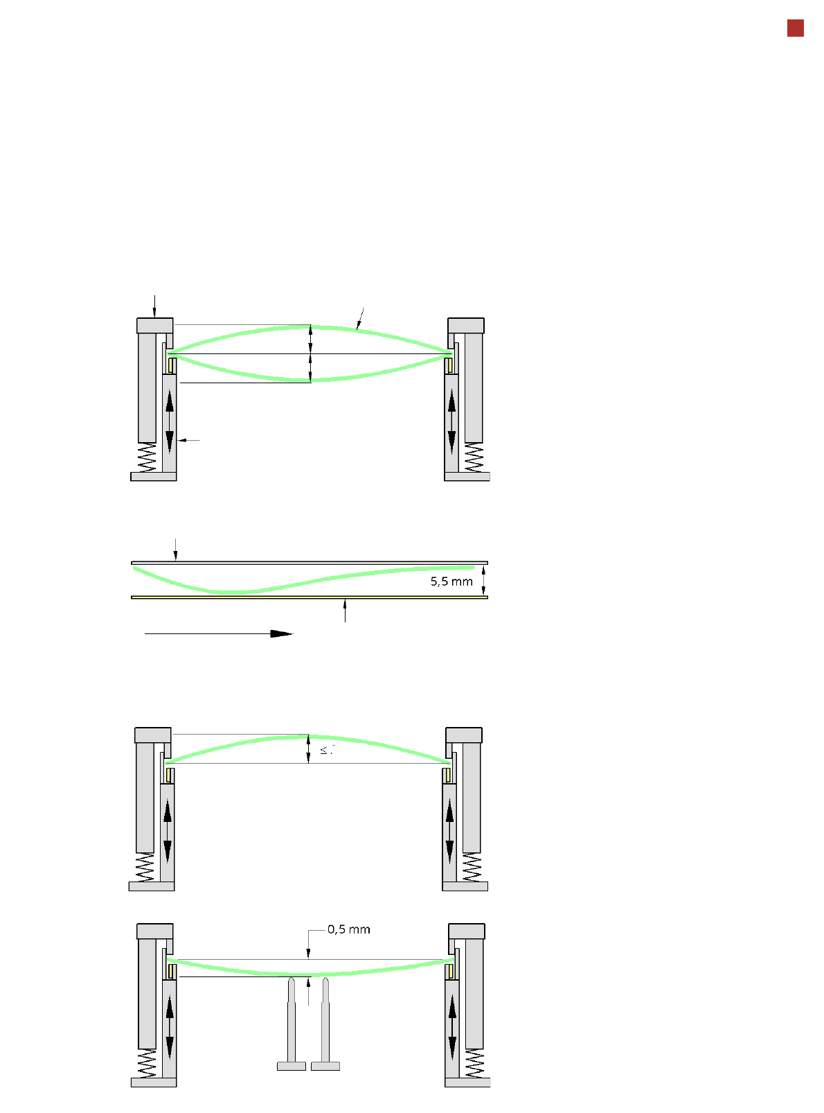
PCB warpage during placement
PCB transport direction
PCB warpage downwards, max. 0.5 mm
Use magnetic pin supports to achieve this
value.
Conveyor belt
Fixed clamped edge
PCB warpage in direction of travel
+ PCB thickness < 5.5 mm
Fixed clamped edge
Movable clamping device
A warpage of 0.5 mm can lead to problems
focussing on local fiducials and ink spots in
the middle of the PCB. The focus of the dig-
ital
camera is 2 mm. When all the tolerances
are taken into account, this value is reduced
to 1.5 mm.
You should also note that the warpage also
reduces the component height.
Magnetic pin support
PCB
0.5 mm
0.5 mm
0.5 mm