Specification SIPLACE CA-Series2011版 - 第33页
33 Sample Configuration Services As an additional service, ASM can prov ide complete integration of your SIPLACE CA machine in your production line. With our extensive exp ertise and by using the right tools and equipmen…
32
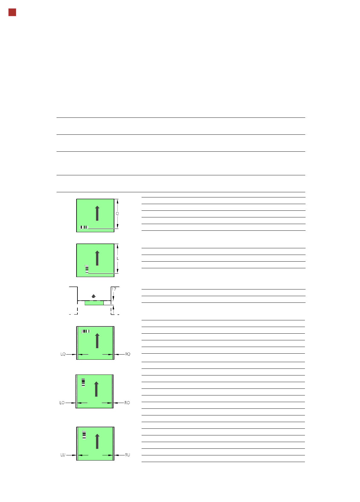
PCB Barcode for Product-Controlled Production
(Option)
Label dimensions Stoke width (B): 0.19 < B 0.3 mm (corresponds to high and medium thick-
ness), barcode length: mm, length of scanning window: 90 mm
Recommended label
colors
Coding: black, dark green, dark blue, background: white, beige, yellow, orange
(contrast ratio > 70% acc. to DIN 66236)
Code types Code 39, Code 128 / EAN 128, Codabar, 2/5 IATA 2/5 industrial, 2/5 inter-
leaved, UPC, EAN, Pharma Code, EAN Addendum (others on request), defini-
tion of a barcode filter possible
Laser scanner safety Laser diode 670 nm (red) / 1.2 mW
Laser protection class 2, degree of protection IP65
Downstream
machine
Upstream
machine
PCB
PCB barcode scanner 1D on top
PCB barcode scanner 1D on bottom
PCB barcode scanner Q [mm]
2D on top 390
1D on top 390
2D on bottom 430
1D on bottom 430
PCB barcode scanner L [mm]
1D on top 320 - 350
1D on bottom 380 - 410
PCB barcode scanner PCB rear projection [mm]
2D on bottom (dual conveyor) 17
PCB barcode scanner LQ [mm] RQ [mm]
2D on top 3 3
1D on top 3 3
2D on bottom 5 5
1D on bottom 5 5
PCB dimensions/conveyor LO [mm] RO [mm]
460 mm SC 3 20
508 mm SC 3 44
216 mm DC1 3 24
250 mm DC1, 450 mm SM1 3 58
216 mm DC2 3 3
250 mm DC2, 450 mm SM2 3 3
PCB dimensions/conveyor LU [mm] RU [mm]
460 mm SC 20 3
508 mm SC 44 3
216 mm DC1 3 3
250 mm DC1, 450 mm SM1 3 3
216 mm DC2 24 3
250 mm DC2, 450 mm SM2 58 3
SC - Single conveyor, DC1/2 - Dual conveyor, track 1/2, SM1/2 - Dual conveyor in Single conveyor mode, track 1/2
If there is a PCB dual conveyor installed on the placement machine, we can provide a special design for
retrofitting the 2D PCB barcode scanner "bottom".
33
Sample Configuration
Services
As an additional service,
ASM can provide complete
integration of your
SIPLACE CA machine in
your production line. With our
extensive expertise and by
using the right tools and
equipment, we can ensure
that the installation process
runs smoothly and efficiently.
However, this requires that
you clarify the infrastructure
aspects in advance and
make any necessary chang-
es at your production facility.
Safety instructions
Read the operating instruc-
tions before starting to set up
and commission the place-
ment machine. The applica-
ble accident prevention
regulations concerning the
transportation of heavy
goods must be followed.
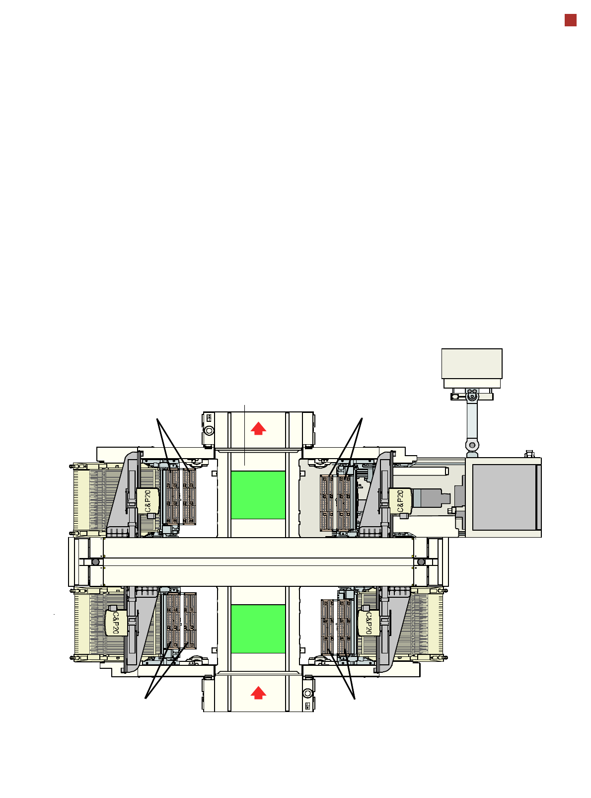
1
2
4
3
2
3
4
1
PCB transport direction
Nozzle changer C&P20
Nozzle changer C&P20
SIPLACE X changeover
table with 40 locations
Nozzle changer C&P20
5-part conveyor belt
with automatic width adjustment
from 50 mm to 508 mm (2“ to 20“)
Nozzle changer C&P20
34
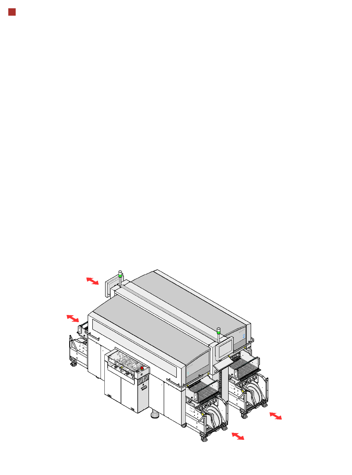
Component Supply
Component Trolley for SIPLACE X-Series
Description
The component trolleys are
independent modules, which
can be configured at an ex-
ternal set-up location with
feeder modules. Up to four
component trolleys can be
docked onto the machine. A
component changeover table
can be replaced with just a
short interruption of the pro-
duction process. The chassis
runs smoothly and is easy to
maneuver.
The changeover table has a
capacity of up to 40 locations
for 8 mm X tape feeder mod-
ules. The total capacity with
four component trolleys is
thus 160 x 8 mm
tracks.
Dummy feeder modules are
used at unassigned locations
to protect the operators.
The component feeders are
at rest during the placement
process - allowing tapes to
be spliced without stopping
the machine.
If an optional component bar-
code reader and the Setup
Center option are installed, it
is possible to read and check
the barcodes on the tape
reels thus guaranteeing that
the components are allocat-
ed to the correct tracks.
Location 1
Location 3
Location 2
Location 4