Specification SIPLACE CA-Series2011版 - 第34页
34 Component Supply Component Trolley for SIPLACE X-Series Description The component trolleys ar e independent modules, which can be configured at an ex- ternal se t-up locatio n with feeder mo dules. Up to four componen…
33
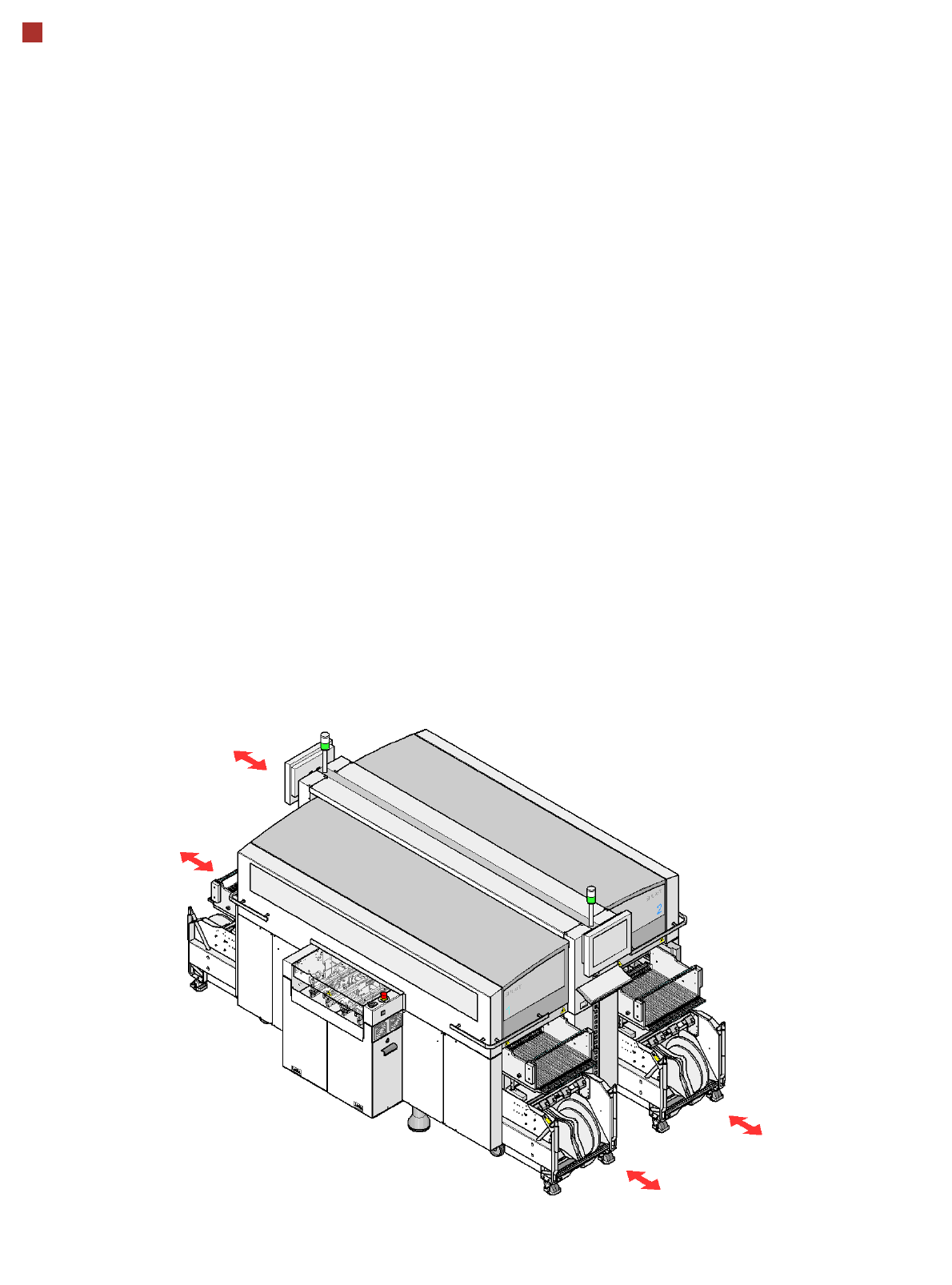
Sample Configuration
Services
As an additional service,
ASM can provide complete
integration of your
SIPLACE CA machine in
your production line. With our
extensive expertise and by
using the right tools and
equipment, we can ensure
that the installation process
runs smoothly and efficiently.
However, this requires that
you clarify the infrastructure
aspects in advance and
make any necessary chang-
es at your production facility.
Safety instructions
Read the operating instruc-
tions before starting to set up
and commission the place-
ment machine. The applica-
ble accident prevention
regulations concerning the
transportation of heavy
goods must be followed.
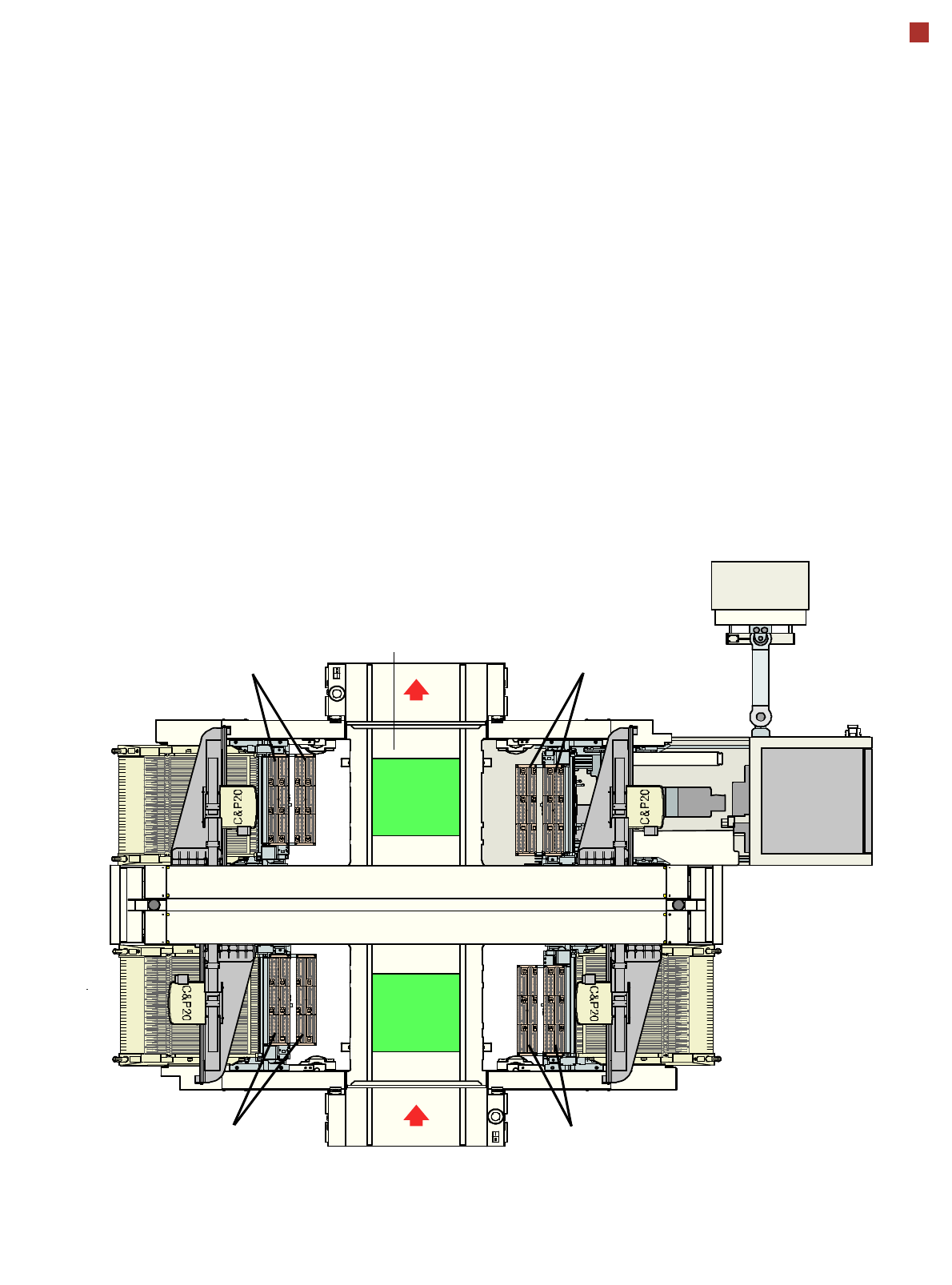
1
2
4
3
2
3
4
1
PCB transport direction
Nozzle changer C&P20
Nozzle changer C&P20
SIPLACE X changeover
table with 40 locations
Nozzle changer C&P20
5-part conveyor belt
with automatic width adjustment
from 50 mm to 508 mm (2“ to 20“)
Nozzle changer C&P20
34
Component Supply
Component Trolley for SIPLACE X-Series
Description
The component trolleys are
independent modules, which
can be configured at an ex-
ternal set-up location with
feeder modules. Up to four
component trolleys can be
docked onto the machine. A
component changeover table
can be replaced with just a
short interruption of the pro-
duction process. The chassis
runs smoothly and is easy to
maneuver.
The changeover table has a
capacity of up to 40 locations
for 8 mm X tape feeder mod-
ules. The total capacity with
four component trolleys is
thus 160 x 8 mm
tracks.
Dummy feeder modules are
used at unassigned locations
to protect the operators.
The component feeders are
at rest during the placement
process - allowing tapes to
be spliced without stopping
the machine.
If an optional component bar-
code reader and the Setup
Center option are installed, it
is possible to read and check
the barcodes on the tape
reels thus guaranteeing that
the components are allocat-
ed to the correct tracks.
Location 1
Location 3
Location 2
Location 4
35
Component supply
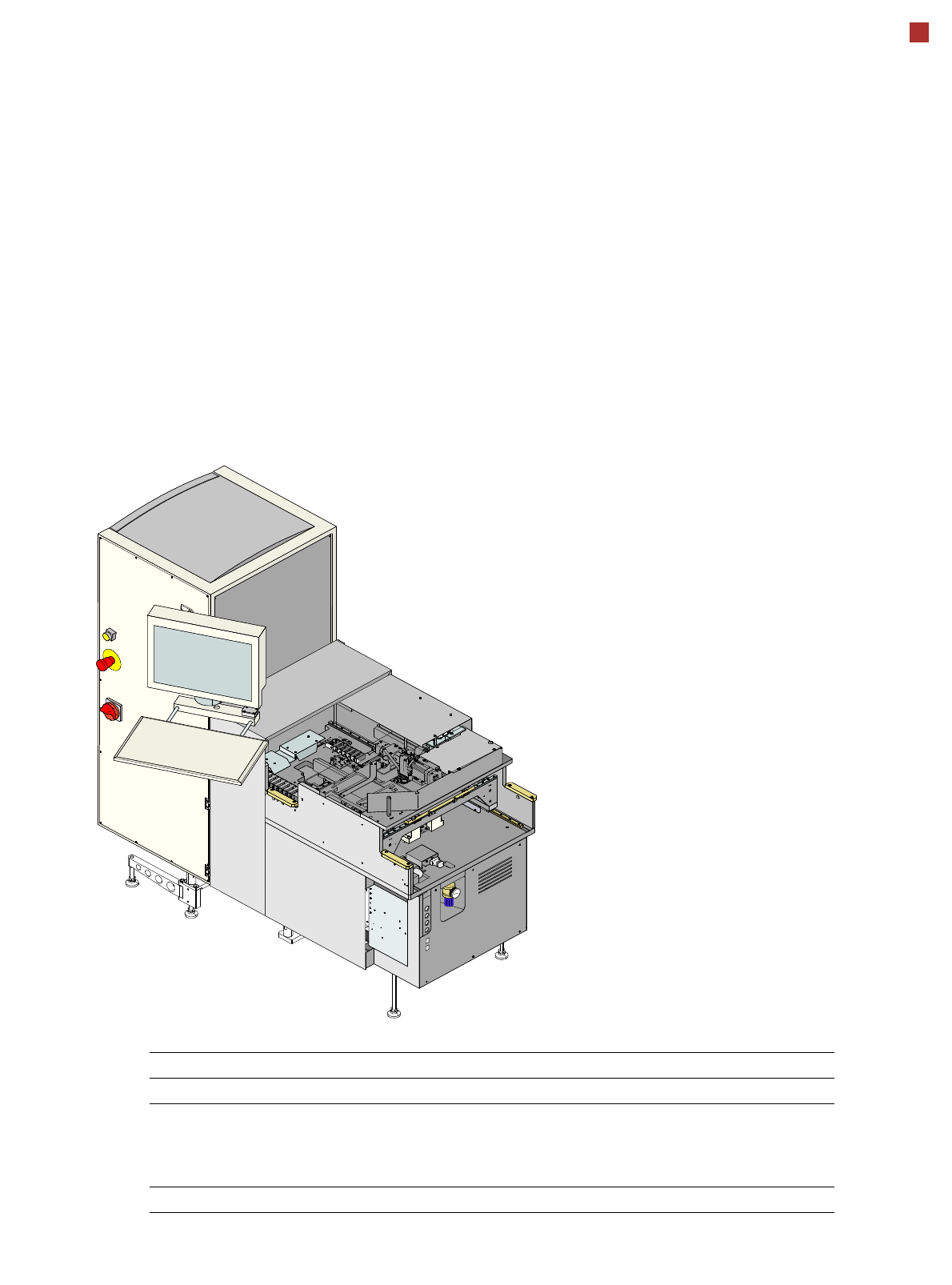
SIPLACE Wafer System
The new SIPLACE Wafer
System (SWS) provides a
fully automatic wafer and
chip handling system.
The SWS is completely inte-
grated into the locations of
the SIPLACE CA placement
system. Each location can be
equipped with an SWS or an
X table.
The SWS functions like a
feeder for the SIPLACE sys-
tem and transports the dies
from the wafer to a single,
fixed pickup position for the
placement head.
The placement head then
picks up the die from the
SWS tool and places this on
the board, just like in SMD
handling.
The SWS is shown as a spe-
cial feeder type in
SIPLACE Pro. The
SIPLACE CA system is pro-
grammed as usual for the SI-
PLACE X series.
The die handling is pro-
grammed via the SWS GUI.
The main parameters to be
programmed are as follows:
– Wafer and die dimen-
sions
– Die recognition
– Die ejection parameters
– Wafer map system
– Link to the component
programmed in
SIPLACE Pro
SWS
Length x width 1.580 mm x 720 mm
PCB transport height 830 mm ± 15 mm (standard)
900 mm ± 15 mm (option)
930 mm ± 15 mm (option)
950 mm ± 15 mm (SMEMA option)
Weight 300 kg
Technical data