Specification SIPLACE CA-Series2011版 - 第46页
46 Technical data SMEMA Interface - Signal Sequence 1. After swit ching on t he statio n Transport direction Belt n Belt n+1 PCB sensor PCB sensor Station n transports PCB to the transfer position Belt n running Belt n+1…

45
Technical data
SMEMA Interface - Connector Assignment
Signal interface (14-pole connecting socket, interface standard 1.2)
Upstream station X1 Downstream station X2
Pin 1 NOT READY + Pin 1 NOT READY +
Pin 2 NOT READY – Pin 2 NOT READY –
Pin 3 BOARD AVAILABLE + Pin 3 BOARD AVAILABLE +
Pin 4 BOARD AVAILABLE – Pin 4 BOARD AVAILABLE –
Pin 5 Not used Pin 5 Not used
Pin 6 Not used Pin 6 Not used
Pin 7 Not used Pin 7 Not used
Pin 8 Reserved Pin 8 Reserved
Pin 9 Reserved Pin 9 Reserved
Pin 10 Reserved Pin 10 Reserved
Pin 11 Reserved Pin 11 Reserved
Pin 12 Reserved Pin 12 Reserved
Pin 13 Reserved Pin 13 Reserved
Pin 14 Reserved Pin 14 Reserved
46
Technical data
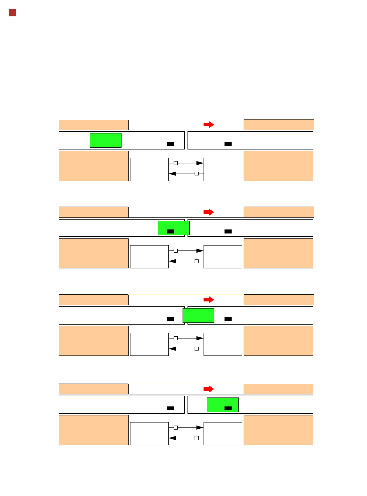
SMEMA Interface - Signal Sequence
1. After switching on the station
Transport direction
Belt n Belt n+1
PCB sensor PCB sensor
Station n transports PCB
to the transfer position
Belt n running Belt n+1 stopped
BOARD AVAIL-
ABLE
Permission
Station n+1
is not ready
1
0
2. The PCB transfer has started
Transport direction
Belt n Belt n+1
PCB sensor
Station n transfers
PCB to Station n+1
Belt n running Belt n+1 running
Station n+1 expects
PCB from station n
3. PCB is transferred
Transport direction
Belt n Belt n+1
PCB sensor PCB sensor
Station n has
just transferred the PCB
Belt n stopped Belt n+1 running
Station n+1 expects PCB
from station n, but PCB
has not yet arrived.
PCB sensor
4. PCB transfer is complete
Transport direction
Belt n Belt n+1
PCB sensor PCB sensor
Station n
Belt n stopped Belt n+1 running
Station n+1
PCB arrived
Request
NOT READY
BOARD AVAIL-
ABLE
Permission
1
1
Request
NOT READY
BOARD AVAIL-
ABLE
Permission
0
1
Request
NOT READY
BOARD AVAIL-
ABLE
Permission
0
0
Request
NOT READY
To start a new PCB transfer, both signals must be "0" for at least 50 ms.

47
Technical data
Electrical Ratings and Compressed Air Supply
Electrical ratings
Supply voltage 3 x 208 V~ ± 5 %; 50/60 Hz (U.S.A)
3 x 230 V~ ± 5 %; 50/60 Hz
3 x 380 V~ ± 5 %; 50/60 Hz
3 x 400 V~ ± 5 %; 50/60 Hz (Europe)
3 x 415 V~ ± 5 %; 50/60 Hz
Fuse protection (machine) 3 x 32 A (3 x 208 VAC / 3 x 230 VAC)
3 x 16 A (3 x 380 VAC / 3 x 400 VAC / 3 x 415 VAC)
Fuse protection (SWS) 3 x 16 A (3 x 208 V~ / 3 x 230 V ~ / 3 x 380 V~ / 3 x 400 V~ / 3 x 415 V~)
Nominal apparent power SIPLACE CA4: 4.7 kVA
SIPLACE CA3: 4.1 kVA
SWS: 0.7 kVA
Rated current consumption SIPLACE CA4: 11,3 A / 3 x 400 V~
SIPLACE CA3: 9.7 A / 3 x 400 V~
SWS: approx. 1.8 A / 3 x 400 V~
Power failure max. 20 ms
Compressed air supply
Compressed air ratings
p
min
p
max
0.5 MPa = 5.0 bar
1.0 MPa = 10 bar
Operating pressure 0.48 MPa ± 0.025 MPa (4.8 bar ± 0.25 bar)
Compressed air connection R 3/4" internal thread (pipe thread) with 1/2" hose connector
Vacuum pump (SWS)
a
a) A vacuum pump is available as an option for the placement head (see also: Retrofit Guide for Vacuum Pump
[00195089-01])
The vacuum pump is integrated into the SWS.
End vacuum: 100 mbar abs
b
Startup: against vacuum
b) Measured with air at 20°C.
Type of machine Placement head configuration Compressed air
consumption
c
without vacuum pump
c) Under normal atmospheric conditions at 20°C and 1013 hPa
SIPLACE CA4
SIPLACE CA3
C&P20CA / C&P20CA / C&P20CA / C&P20CA
C&P20CA / C&P20CA / C&P12CA / C&P12CA
C&P20CA / C&P20CA / C&P6CA / C&P6CA
C&P20CA / C&P20CA / C&P6CA / C&P12CA
C&P20CA / C&P20CA / C&P20CA
C&P20CA / C&P20CA / C&P12CA
C&P20CA / C&P20CA / C&P6CA
990 Nl/min
970 Nl/min
970 Nl/min
970 Nl/min
780 Nl/min
760 Nl/min
760 Nl/min
Compressed air specification
Particle size 5 µm
Particle density 5 mg/m³
Maximum oil content
(class 1)
Particle density 0.01 mg/m³
Pressure dewpoint (class 4) Dewpoint + 3°