Specification SIPLACE CA-Series2011版 - 第60页
60 Option List Placement Machine Available options CA4 CA3 Notes PCB alignment, single conveyor X X PCB alignment, dual conveyor X X Long board X X Mechanical stopper X X Multicolor PCB camera, type 24, digital X X 1D PC…
59
Technical data
Transportation and Delivery Conditions for
SWS
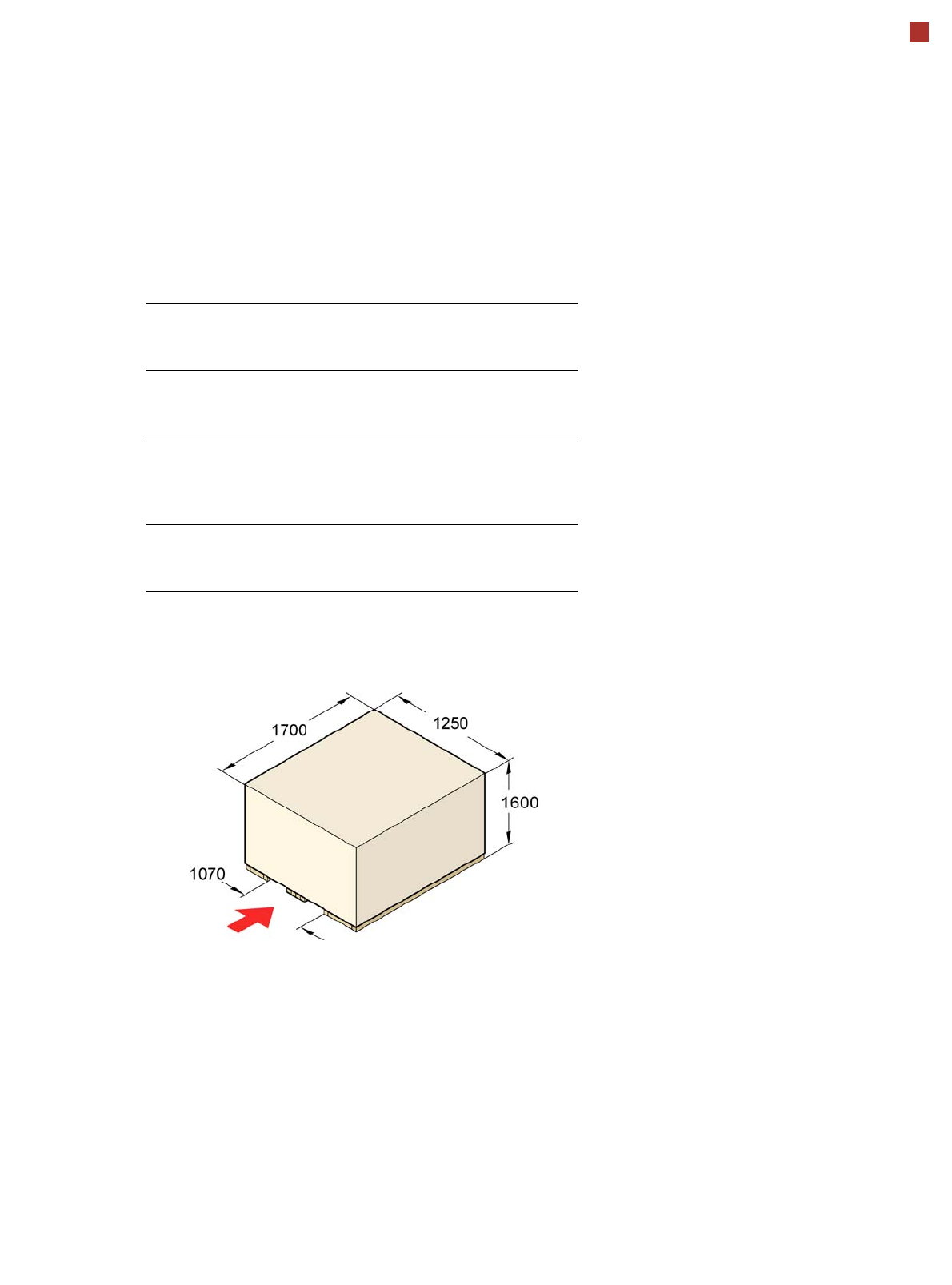
Transport dimensions and weight
Means of transport
A fork-lift truck with the following specification will be needed
to carry the machine in its crate:
Length
Width
Height
1700 mm
1250 mm
1600 mm
Weight
SWS 12
Dispatch Dispatch
within Europe overseas
390 kg 473 kg
Fork length
Lifting power
Clear fork width
min. 1800 mm
min. 1500 kg
min. 350 mm
Description
Within Europe, the machine
is delivered on a robust
wooden pallet. If sent over-
seas, the SWS is packaged
in a wooden crate.
Engagement point
for the fork-lift

60
Option List
Placement Machine
Available options CA4 CA3 Notes
PCB alignment, single conveyor X X
PCB alignment, dual conveyor X X
Long board X X
Mechanical stopper X X
Multicolor PCB camera, type 24, digital X X
1D PCB barcode scanner X X
2D PCB barcode scanner X X
PCB barcode scanner assembly kit X X
Magnetic pin support X X
20 segment Collect&Place CA head X X In the two-gantry area, only in combination
with another 20 segment Collect & Place CA
head
01005 components X X
12 segment Collect&Place head X X
High-resolution component camera, type 29
for C&P12
XX
Component sensor C&P12 X X
0201 package X X
6 segment Collect&Place head X X
TwinHead X X Only possible in placement area without
SWS
High-Force Head X X Only possible in placement area without
SWS
Stationary component camera, type 25, 16
x 16, digital
X X For the TwinHead or High-Force Head only
Vision teach station X X
Coplanarity module – X For the TwinHead or High-Force Head at
location 3 only
3D coplanarity module – X For the TwinHead or High-Force Head at
location 3 only
Nozzle Changers X X Depending on the placement head
Sensor for the component reject bin X X
Component Trolley for SIPLACE X-Series X X
Splice detection for X feeder modules X X

61
Option List
Placement Machine
Available options CA4 CA3 Notes
Waffle pack tray holder
SIPLACE X series
X X Can be used at locations 2 and 4 but
only with the SIPLACE X series component
trolleys; not in combination
with the C&P20 CA placement
head
Support for an additional tape reel
SIPLACE X-series
XX
Feeder adapter for X series X X S linear vibratory feeders and label presenter
modules can be set up on component
trolleys for the SIPLACE X series using
this adapter.
Linear Dipping Unit (LDU) X X
Integrated into SWS 12 and/or on X table, although
only one LDU per location.
Feeder module cover flap X X
110/208 V conversion kit X X
Vacuum pump
a
X X Not for the TwinHead or High-Force Head
Vacuum pump connection kit X X
Productivity lift X X Maximum PCB width:
- single lane 460 mm
- double lane 216 mm
Maximum component height: 17 mm on the
underfloor section
a) Operation with vacuum pump only possible with software SR.605.03