Specification SIPLACE CA-Series2011版 - 第8页
8 Machine Description Technical Data - SMT Placement head types – 20 segment Collect&Place CA head (C&P20CA) – 12 segment Collect&Place CA head (C&P12A) – 6 segment Collect&Place CA head (C&P6) – …
7
Machine Description
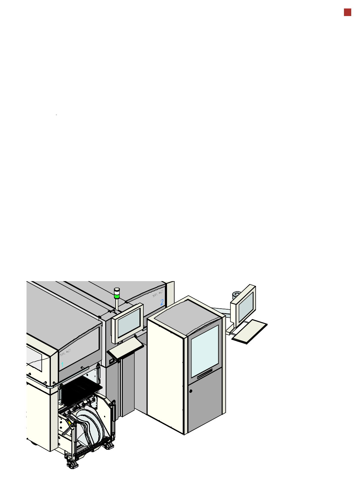
SIPLACE Wafer System
Description
The SIPLACE Wafer System
(SWS) makes the compo-
nents available to the place-
ment head, directly from the
wafer. The SWS therefore
extends the component
spectrum of the established
SIPLACE X machines, by
enabling placement of bare
dies from wafers.
The wafers are supplied fully
automatically out of the wafer
cassette and the dies inside
can be processed in the
established placement pro-
cedures.
Flip chip process - func-
tion
The wafer is fully automati-
cally pulled out of the wafer
cassette and is then trans-
ported to the wafer table. The
wafer table positions the die
above the ejection system
that releases the die from the
wafer foil. After this release
procedure, the flip unit noz-
zle takes the die, rotates it by
180° and makes it available
to the placement head for
pickup.
Options
The process spectrum is
supplemented by the follow-
ing options:
– Die Attach Unit:
The die attach unit takes
the die from the flip unit
nozzle and turns it, so that
it has the same top-bottom
orientation on the board
as it had on the wafer.
– Linear Dipping Unit
The Linear Dipping Unit
distributes precise layers
of flux for the flip chip pro-
cess. After the dies have
been taken over from the
flip unit, the placement
head dips the dies into the
layer of flux.

8
Machine Description
Technical Data - SMT
Placement head
types
– 20 segment Collect&Place CA head (C&P20CA)
– 12 segment Collect&Place CA head (C&P12A)
– 6 segment Collect&Place CA head (C&P6)
– SIPLACE TwinHead (TH)
(only possible in a placement area without SWS).
Number of gan-
tries
CA4: 4 gantries
CA3: 3 gantries
Placement posi-
tion
6,000 / gantry for the Collect&Place heads
2,000 / gantry for the TwinHead
Component spec-
trum
a
a) The range of components depends on which head configuration is selected.
0.4 mm x 0.2 mm (01005), 0.6 mm x 0.3 mm (0201)
to 85 mm x 85 mm / 125 mm x 10 mm,
max. 200 mm x 125 mm (with restrictions)
Component
height
C&P20CA: 4 mm
C&P12: 6 mm
C&P6: 8.5 mm
TH: 25 mm
b
(higher heights on request)
b) The specified component height for TwinHead might be reduced in placement areas with two gantries and a combination
of Collect&Place head and TwinHead.
Placement accu-
racy
(Standard criteria
for SMD)
C&P20CA
C&P12
C&P6
TH
TH
± 41 µm (3), ± 55 µm (4)
± 41 µm (3), ± 55 µm (4)
± 45 µm (3), ± 60 µm (4)
± 26 µm (3), ± 35 µm (4)
± 22 µm (3), ± 30 µm (4)
Component camera, type 41 (6 x 6)
Component camera, type 29 (27 x 27)
Component camera, type 29 (27 x 27)
Component camera, type 33 (55 x 45)
Component camera, type 25 (16 x 16)
Placement accu-
racy
(Advanced crite-
ria for SWS)
C&P20CA
C&P12
C&P6
TH
TH
± 25 µm (3), ± 33 µm (4)
± 25 µm (3), ± 33 µm (4)
± 35 µm (3), ± 47 µm (4)
± 26 µm (3), ± 35 µm (4)
± 22 µm (3), ± 30 µm (4)
Component camera, type 41 (6 x 6)
Component camera, type 29 (27 x 27)
Component camera, type 29 (27 x 27)
Component camera, type 33 (55 x 45)
Component camera, type 25 (16 x 16)
Angular accuracy C&P20CA
C&P12
C&P6
TH
TH
± 0.5° (3), ± 0.7° (4)
± 0.5° (3), ± 0.7° (4)
± 0.2° (3), ± 0.3° (4)
± 0.05° (3), ± 0.07° (4)
± 0.05° (3), ± 0.07° (4
)
Component camera, type 41 (6 x 6)
Component camera, type 29 (27 x 27)
Component camera, type 29 (27 x 27)
Component camera, type 33 (55 x 45)
Component camera, type 25 (16 x 16)

9
Machine Description
Technical Data - SMT
Component supply – SIPLACE CA4: Up to four SWS
a
possible in placement area 1 and 2
– SIPLACE CA3: Two SWS
a
possible in placement area 1
– Component trolley (X series)
(with tape reel holder and integrated waste tape bin,
40 locations, each with 8 mm X feeders per component trolley)
– Matrix Tray Changer
b
(on request)
Feeder module types – X series component trolley: tapes, waffle pack trays
Supply capacity
(component
trolley
X series)
160 tracks Width: 8 mm 8 mm X feeder modules
80 tracks Width: 12 mm 12 mm X feeder modules
52 tracks Width: 16 mm 16 mm X feeder modules
52 tracks Width: 24 mm 24 mm X feeder modules
40 tracks Width: 32 mm 32 mm X feeder modules
32 tracks Width: 44 mm 44 mm X feeder modules
24 tracks Width: 56 mm 56 mm X feeder modules
20 tracks Width: 72 mm 72 mm X feeder modules
16 tracks Width: 88 mm 88 mm X feeder modules
Board format
(LxW)
Single conveyor
50 mm x 50 mm to 450 mm x 508 mm
50 mm x 80 mm to 610 mm x 508 mm ("Long board" option)
Dual conveyor
50 mm x 50 mm to 450 mm x 250 mm
50 mm x 80 mm to 610 mm x 250 mm ("Long board" option)
Dual conveyor in single conveyor mode
50 mm x 50 mm to 450 mm x 450 mm
50 mm x 80 mm to 610 mm x 450 mm ("Long board" option)
PCB thickness 0.3 - 4.5 mm (standard, thicker boards on request)
Vacuum tooling on request
Thin PCBs on a carrier
a) No combination of SWS and TwinHead possible
b) The Matrix Tray Changer can only be used at locations 2 and 4.