Specification SIPLACE CA-Series2011版 - 第9页
9 Machine Description Technical Data - SMT Component supply – SIPLACE CA4: Up to four SWS a possible in placement area 1 and 2 – SIPLACE CA3: T wo SWS a possible in placement area 1 – Component trolley (X series) (with t…

8
Machine Description
Technical Data - SMT
Placement head
types
– 20 segment Collect&Place CA head (C&P20CA)
– 12 segment Collect&Place CA head (C&P12A)
– 6 segment Collect&Place CA head (C&P6)
– SIPLACE TwinHead (TH)
(only possible in a placement area without SWS).
Number of gan-
tries
CA4: 4 gantries
CA3: 3 gantries
Placement posi-
tion
6,000 / gantry for the Collect&Place heads
2,000 / gantry for the TwinHead
Component spec-
trum
a
a) The range of components depends on which head configuration is selected.
0.4 mm x 0.2 mm (01005), 0.6 mm x 0.3 mm (0201)
to 85 mm x 85 mm / 125 mm x 10 mm,
max. 200 mm x 125 mm (with restrictions)
Component
height
C&P20CA: 4 mm
C&P12: 6 mm
C&P6: 8.5 mm
TH: 25 mm
b
(higher heights on request)
b) The specified component height for TwinHead might be reduced in placement areas with two gantries and a combination
of Collect&Place head and TwinHead.
Placement accu-
racy
(Standard criteria
for SMD)
C&P20CA
C&P12
C&P6
TH
TH
± 41 µm (3), ± 55 µm (4)
± 41 µm (3), ± 55 µm (4)
± 45 µm (3), ± 60 µm (4)
± 26 µm (3), ± 35 µm (4)
± 22 µm (3), ± 30 µm (4)
Component camera, type 41 (6 x 6)
Component camera, type 29 (27 x 27)
Component camera, type 29 (27 x 27)
Component camera, type 33 (55 x 45)
Component camera, type 25 (16 x 16)
Placement accu-
racy
(Advanced crite-
ria for SWS)
C&P20CA
C&P12
C&P6
TH
TH
± 25 µm (3), ± 33 µm (4)
± 25 µm (3), ± 33 µm (4)
± 35 µm (3), ± 47 µm (4)
± 26 µm (3), ± 35 µm (4)
± 22 µm (3), ± 30 µm (4)
Component camera, type 41 (6 x 6)
Component camera, type 29 (27 x 27)
Component camera, type 29 (27 x 27)
Component camera, type 33 (55 x 45)
Component camera, type 25 (16 x 16)
Angular accuracy C&P20CA
C&P12
C&P6
TH
TH
± 0.5° (3), ± 0.7° (4)
± 0.5° (3), ± 0.7° (4)
± 0.2° (3), ± 0.3° (4)
± 0.05° (3), ± 0.07° (4)
± 0.05° (3), ± 0.07° (4
)
Component camera, type 41 (6 x 6)
Component camera, type 29 (27 x 27)
Component camera, type 29 (27 x 27)
Component camera, type 33 (55 x 45)
Component camera, type 25 (16 x 16)

9
Machine Description
Technical Data - SMT
Component supply – SIPLACE CA4: Up to four SWS
a
possible in placement area 1 and 2
– SIPLACE CA3: Two SWS
a
possible in placement area 1
– Component trolley (X series)
(with tape reel holder and integrated waste tape bin,
40 locations, each with 8 mm X feeders per component trolley)
– Matrix Tray Changer
b
(on request)
Feeder module types – X series component trolley: tapes, waffle pack trays
Supply capacity
(component
trolley
X series)
160 tracks Width: 8 mm 8 mm X feeder modules
80 tracks Width: 12 mm 12 mm X feeder modules
52 tracks Width: 16 mm 16 mm X feeder modules
52 tracks Width: 24 mm 24 mm X feeder modules
40 tracks Width: 32 mm 32 mm X feeder modules
32 tracks Width: 44 mm 44 mm X feeder modules
24 tracks Width: 56 mm 56 mm X feeder modules
20 tracks Width: 72 mm 72 mm X feeder modules
16 tracks Width: 88 mm 88 mm X feeder modules
Board format
(LxW)
Single conveyor
50 mm x 50 mm to 450 mm x 508 mm
50 mm x 80 mm to 610 mm x 508 mm ("Long board" option)
Dual conveyor
50 mm x 50 mm to 450 mm x 250 mm
50 mm x 80 mm to 610 mm x 250 mm ("Long board" option)
Dual conveyor in single conveyor mode
50 mm x 50 mm to 450 mm x 450 mm
50 mm x 80 mm to 610 mm x 450 mm ("Long board" option)
PCB thickness 0.3 - 4.5 mm (standard, thicker boards on request)
Vacuum tooling on request
Thin PCBs on a carrier
a) No combination of SWS and TwinHead possible
b) The Matrix Tray Changer can only be used at locations 2 and 4.
10
Machine Description
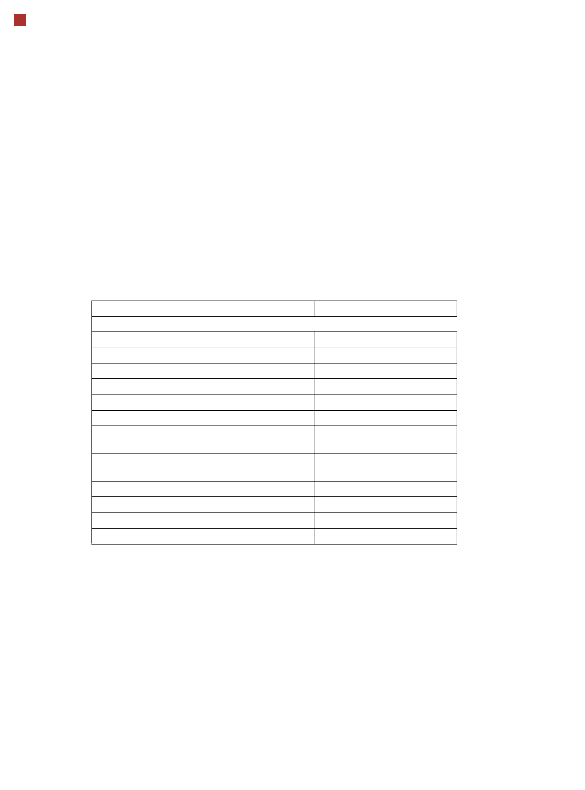
Machine Performance
The following table lists the benchmark values (as defined in "Scope of Service and
Delivery SIPLACE CA") for SMT placement in each placement area. As the benchmark
test for the TwinHead and the C&P heads uses different components, the benchmark
values for the TwinHead and C&P heads must be specified separately. However, the
joint component spectrum can still be processed by both the TwinHead and the Col-
lect&Place heads in the same production environment.
Placement heads in placement area (PA) Placement rate [comp./h]
SMD Application
C&P20CA and C&P20CA 40,000 cph ± 3 %
C&P12 and C&P12 26,400 cph ± 3 %
C&P12 and C&P6 20,300 cph ± 3 %
C&P6 and C&P12 20,300 cph ± 3 %
C&P6 and C&P6 18,300 cph ± 3 %
TH and TH 5,800 cph ± 3 %
C&P12 and TH C&P12: 14,000 cph ± 3 %
TH: 3,300 cph ± 3 %
C&P6 and TH C&P6: 9,800 cph ± 3 %
TH: 3,300 cph ± 3 %
C&P20CA 20,000 cph ± 3 %
C&P12 14,000 cph ± 3 %
C&P6 9,800 cph ± 3 %
TH 3,700 cph ± 3 %
Die placement depends on several process-specific parameters. The expected
throughput can be individually calculated on request.
The benchmark values for one SWS and a die size of 1x1mm are:
In “Flip Chip” mode: 9.000 dies / h without flux dipping
In “Flip Chip” mode: 6.000 dies / h with flux dipping
In “Die Attach” mode (on request): 6.000 dies / h
See also page 11.