YSM10安装调整(eng).pdf - 第102页
For Ser v ice E n gineer Service Information SI1610004E -000= YSM10_Proced ures for the adjustmen ts required after installing a machine 102/107 11.3.7 Multi camera – “Lightness” adj ustment (O ption) Light adjuster T …
For Service Engineer
Service Information
SI1610004E-000= YSM10_Procedures for the adjustments required after installing a machine
101/107
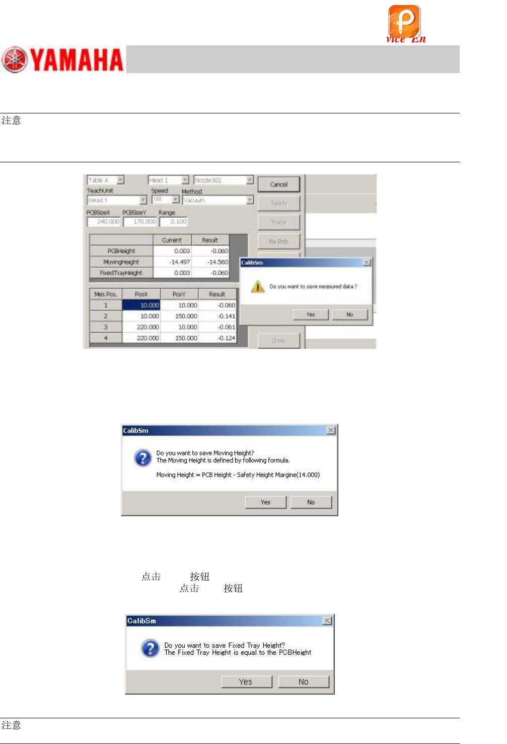
9. Save the measurement results.
:
If the difference between the maximum and the minimum values of the PCB height exceeds the
specified value, the message appears.
Check if the board is clamped properly, and then perform the adjustment again.
Figure 150
10. Check if the “Moving Height” value needs to be changed.
After saving the “PCB Height” data, the message appears asking you to save the “Moving Height”
value. As the value is calculated automatically, save the data without change except for when the
special setting is done.
Figure 151
11. Check if the “Fixed Tray Height” value needs to be changed.
After saving the “Moving Height” value, a message appears asking you to save the “Fixed Tray
Height”. Set the coordinate of the “PCB Height” as the default value of the “Fixed Height”. If the
“Fixed Tray” is NOT used,
[Yes] to change the value.
If the “Fixed Tray” is actually used,
[No] and check the “Fixed Tray Height”
separately.
Figure 152
:
Without a 302A, a 313A or a 309A , the automatic adjustment cannot be performed.
该文档是极速PDF编辑器生成,
如果想去掉该提示,请访问并下载:
http://www.jisupdfeditor.com/
For Service Engineer
Service Information
SI1610004E-000= YSM10_Procedures for the adjustments required after installing a machine
102/107
11.3.7 Multi camera – “Lightness” adjustment (Option)
Light adjuster
The “Gray and white” light adjuster is used for performing the “Lightness” adjustment of the Multi
camera.
For the adjustment of the multi camera with an elevator type side light, use a milky white light
adjuster.
:
See “2.1 Jigs for the “Lightness” adjustment of the cameras” for the types of the light adjusters.
Required
For the adjustment of the multi camera with an elevator type side light, a “ 304 (315) is
required.
:
See “2.5 Other jigs required for the adjustment” for the types of the light adjusters.
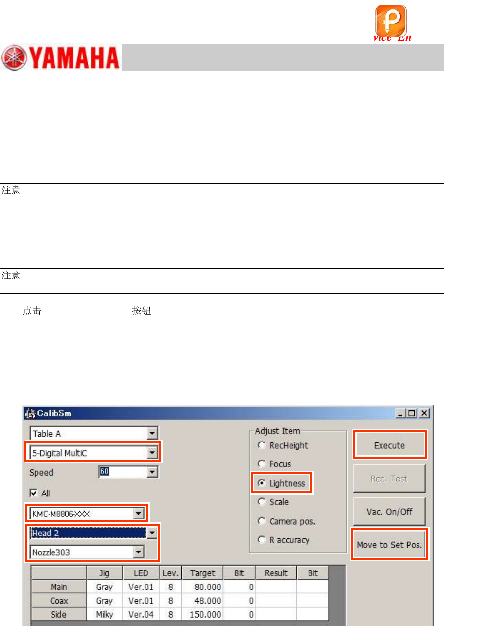
1.
[011 Multi camera] on the CalibSm main menu, and select “Lightness” from
“Adjust Item”.
2. Select the camera to be adjusted.
If the machine is equipped with one (1) Multi camera “5-digital MultiC”
If the machine is equipped with two (2) Multi cameras
<Front>: “5-Digital MultiC” <Rear>: “6-Digital MultiC”
Figure 153
3. Select the light adjuster to be used.
In the “Lightness” adjustment for the main and the coaxial lights, the target value varies depending
on the light adjuster. Make sure to select the part number of the light adjuster that is actually used
for the adjustment.
For the adjustment of the multi camera with an elevator type side light, special jigs are required.
・ Light adjuster: 32mm sq. milky white
・ 304 (315)
Step 2
Step 3
Step 4
Step 1
Step 6
Step 5
该文档是极速PDF编辑器生成,
如果想去掉该提示,请访问并下载:
http://www.jisupdfeditor.com/
For Service Engineer
Service Information
SI1610004E-000= YSM10_Procedures for the adjustments required after installing a machine
103/107
4. Select the head to be used for the adjustment.
When performing the adjustment for the main and the coaxial lights, use either of the 17mm sq. or
the 32mm sq. jig.
As the 32mm sq. milky white light adjuster is used for the adjustment of the side light, select the
head that a 304A(315A) can be attached.
Head numbers that a 304A(315A) can be attached
(For the machines with an ANC)
10-head type
5-head type
304A(315A)
2, 8
2, 5
Table 46
:
If the machine is NOT equipped with an ANC, attach the specified to the selected head. Make
sure that the type displayed on the window is the same as the actually used .
Caution:
Make sure that the attached to the head and the type displayed under the “Head number”
pull-down menu are the same.
As the length of the 304A (315A) and the 303A (314A) are different, if the adjustment is
performed with the different types (the type of the actual and the selected on the
window), it may cause an error in the measured result.
5.
[Move to Set Pos.] to pick up the light adjuster.
If the machine is equipped with an ANC, the of the head selected in step 4 is changed
to the selected , and the head moves to above the front-side feeder bank.
If the machine is NOT equipped with an ANC, the head to be adjusted moves to above the
front-side feeder bank. Put the machine into the “Emergency stop” state, and attach the
selected in step 4 to the head by hand.
6. Set the light adjuster to the .
Make the head suck the light adjuster with its light gray surface facing down.
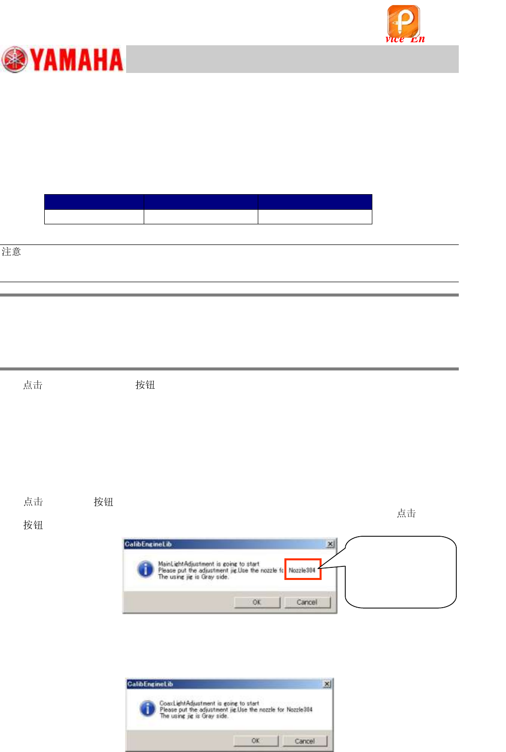
7. [Execute] .
The following window appears. Make sure that the light adjuster is set properly, and
[OK]
to start the adjustment.
Figure 154
8. Perform the adjustment for the coaxial light continuously.
After saving the adjustment result of the main light, perform the lightness adjustment for the
coaxial light according to the instruction on the screen.
Figure 155
Make sure that the
type displayed
here and the actually
used are the
same.
该文档是极速PDF编辑器生成,
如果想去掉该提示,请访问并下载:
http://www.jisupdfeditor.com/