YSM10安装调整(eng).pdf - 第105页
For Ser v ice E n gineer Service Information SI1610004E -000= YSM10_Proced ures for the adjustmen ts required after installing a machine 105/107 When the machine is equi pped with a “ 6-Digital Mu ltiC ” 11. Select “ 6…
For Service Engineer
Service Information
SI1610004E-000= YSM10_Procedures for the adjustments required after installing a machine
104/107
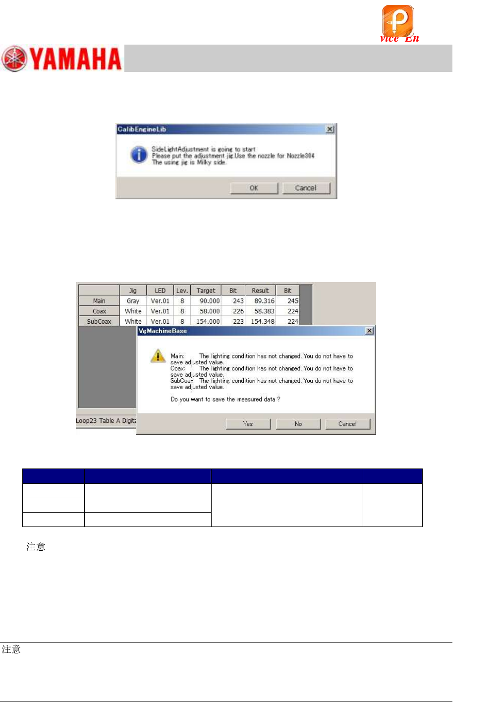
9. Perform the “Lightness” adjustment for the side light continuously.
Attach the milky light adjuster to the head and perform the adjustment.
Figure 156
10. Save the adjusted data.
When the adjustment is completed, a dialog box appears asking you to save the data.
Check if the values in the “Result” and “Bit” fields fall within the specification, and save the data.
If the values meet the specification, fill in the values on the check sheet.
Figure 157
<Specified value>
Light
Color of the Light adjuster
Tolerance of the measured value
Bit value
Main
Gray
Target value +/- 2
128 ~ 656
Coax
Side
Milky white
Table 47
[
]
When the Bit value does not meet the specification, check the following.
・ Is the correct jig (light adjuster) selected?
・ Is the jig (light adjuster) clean? If it is not, clean it with alcohol.
・ Is the lighting environment affecting the adjustment result?
・ Is the lighting condition normal? (Are all the LEDs lit?)
:
As the upper limit of the specified Bit value is the warning value, the adjustment is completed properly
even when the value exceeds the specified value.
If the measured result exceeds 656 (the 7/8 of the limit value), it may attribute to the deterioration of the
lighting device. It is recommended to replace the lighting. (Limit value of the Bit value: 750)
If the machine is equipped with the optional multi camera “6-DigitalMultiC”, perform the adjustment
for the camera continuously.
If the machine is not equipped with the optional camera, go on to step 14.
该文档是极速PDF编辑器生成,
如果想去掉该提示,请访问并下载:
http://www.jisupdfeditor.com/
For Service Engineer
Service Information
SI1610004E-000= YSM10_Procedures for the adjustments required after installing a machine
105/107
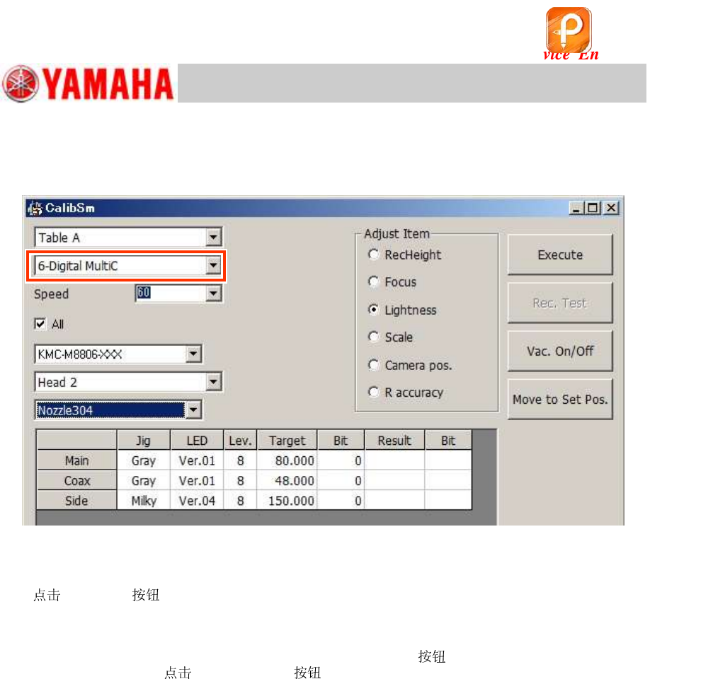
When the machine is equipped with a “6-Digital MultiC”
11. Select “6-Digital MultiC”.
Figure 158
12. Make the head suck the light adjuster with its light gray surface facing down.
13.
[Execute] .
Attach the light adjuster to the head according to the message and perform the adjustment.
14. Remove the light adjuster.
After completing the adjustment, press the [Emergency Stop]
and remove the light adjuster
from the head. Then [Vac. ON/OFF] to turn off the vacuum operation.
If the 304A (315A) (that the machine is not equipped with) was attached manually for the
adjustment, remove it and put the original back to the head.
该文档是极速PDF编辑器生成,
如果想去掉该提示,请访问并下载:
http://www.jisupdfeditor.com/
For Service Engineer
Service Information
SI1610004E-000= YSM10_Procedures for the adjustments required after installing a machine
106/107
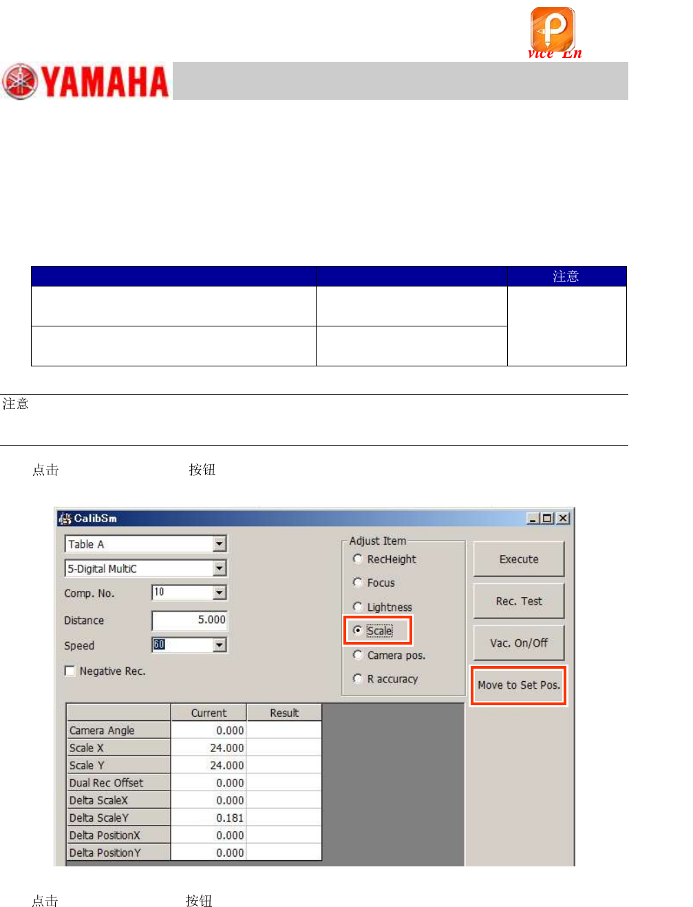
11.3.8 Multi camera – “” adjustment (Option)
If the machine is equipped with an optional multi camera, perform the “” adjustment for the
camera.
・ Required : Type 303A (314A) (For SOP)
・ Required component: Use either of the following.
16-pin QFP
Part No. (MCH_SETUP)
WITHOUT a sticker
(KW8-M880A-00 / QFP 16P)
No.10 (QFP16_P0.8)
Use either of the
QFPs.
WITH a sticker
(KHY-M880A-00 / QFP 16P ASSY)
No.34
(QFP16_P0.8_WHITE)
Table 48
:
When a 16-pin QFP with a sticker is used, select the Part No. 34 and tick the “Negative Rec.”
checkbox.
1.
[011 Multi Camera] on the CalibSm main menu and select “” from
“Adjust Item”.
Figure 159
2.
[Move to Set Pos.] and change the to the 303A (314A) .
If the machine is equipped with an ANC:
The of the head to be adjusted is changed to 303A (314A) automatically and the
head moves to above the front-side feeder bank.
If the machine is NOT equipped with an ANC:
The head moves to above the front-side feeder bank. Put the machine into the “Emergency
Stop” state and attach the 303A (314A) to the head by hand.
该文档是极速PDF编辑器生成,
如果想去掉该提示,请访问并下载:
http://www.jisupdfeditor.com/