YSM10安装调整(eng).pdf - 第18页
For Ser v ice E n gineer Service Information SI1610004E -000= YSM10_Proced ures for the adjustmen ts required after installing a machine 18/107 4.5.2 “ Dual Driv e Offset ” adju stment for th e Y-axis Y : …
For Service Engineer
Service Information
SI1610004E-000= YSM10_Procedures for the adjustments required after installing a machine
17/107
4.5 Axis
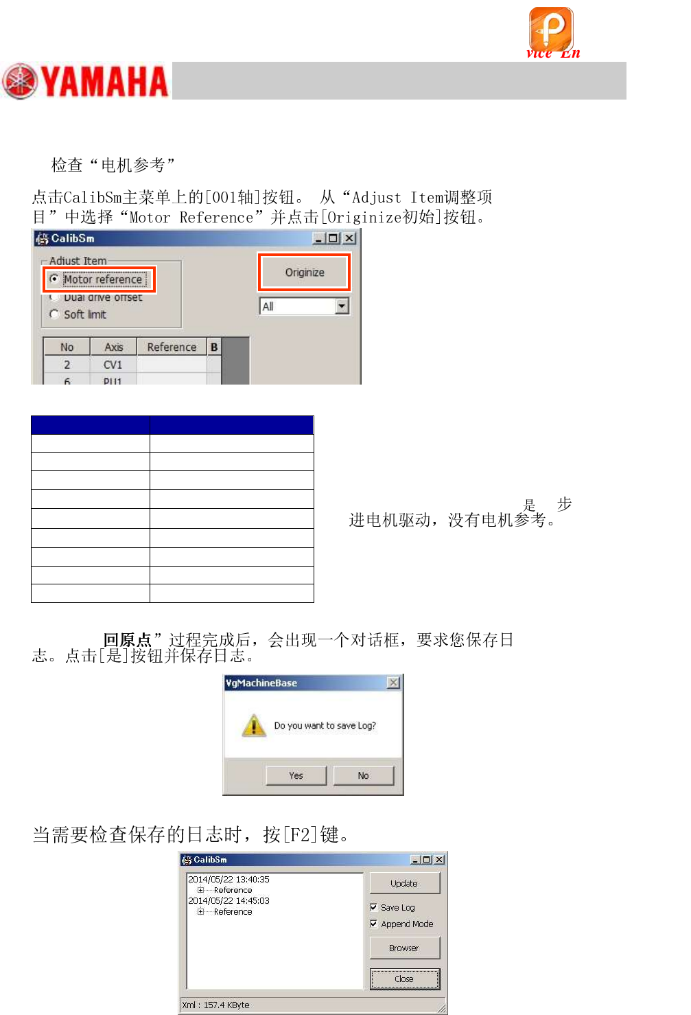
4.5.1
Figure 14
Axis name
X1, Y1
50 +/- 5
ZA1 ~ ZA10
35 +/- 10
RA1, RA2
30 +/- 10
W1
0 *
PU1
0 *
CV1
0 *
SC1
45 +/- 10
AH
50 +/- 5
AZ
50 +/- 5
Table 11
モ
Figure 15
Figure 16
*: As the W1, PU1 and CV1
该文档是极速PDF编辑器生成,
如果想去掉该提示,请访问并下载:
http://www.jisupdfeditor.com/
For Service Engineer
Service Information
SI1610004E-000= YSM10_Procedures for the adjustments required after installing a machine
18/107
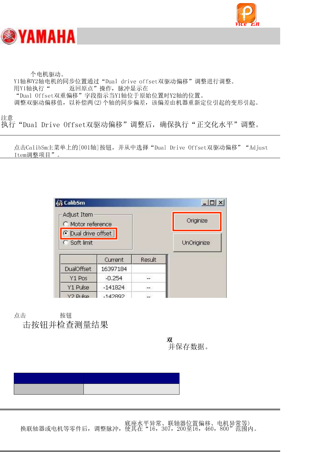
4.5.2 “Dual Drive Offset” adjustment for the Y-axis
Y
:
1.
Fill in the current “Dual Offset” value on the checksheet.
Figure 17
2.
[Originize] .
(“Result” value).
3. Check and save the dual drive offset value.
Y2-axis (Pulse) “”
Fill in the measured value on the checksheet.
Adjustment item
Specified value (%)
Dual Drive Offset
16,128,000 - 16,640,000
Table 12
Caution:
@H
该文档是极速PDF编辑器生成,
如果想去掉该提示,请访问并下载:
http://www.jisupdfeditor.com/
For Service Engineer
Service Information
SI1610004E-000= YSM10_Procedures for the adjustments required after installing a machine
19/107
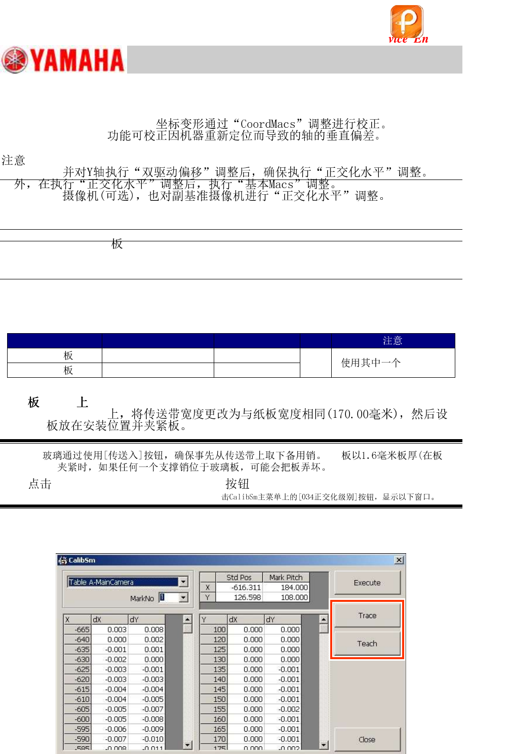
4.6 “Orthogonalization Level” adjustment
xy
モヤ
:
Z@
Jig required for the “Orthogonalization Level “adjustment
*
.
Board
Part Name
Part No.
Qty
ACP
PCB ASSY.4
KM0-M8810-40
1
.
AMF
PCB ASSY.1
KM0-M8810-10
Table 13
1. .
モuョゥエヤ
Caution:
I
2. [034 Orthogonalization level] on the CalibSm main menu
to display the following window.
Figure 18
Step 3
该文档是极速PDF编辑器生成,
如果想去掉该提示,请访问并下载:
http://www.jisupdfeditor.com/