YSM10安装调整(eng).pdf - 第44页
For Ser v ice E n gineer Service Information SI1610004E -000= YSM10_Proced ures for the adjustmen ts required after installing a machine 44/107 6. M ake sure that the 1005 ceramic chip component o n the board can be…
For Service Engineer
Service Information
SI1610004E-000= YSM10_Procedures for the adjustments required after installing a machine
43/107
5.4 Preparation for the ACP-Chip adjustment
Read the board data and perform the recognition check
1. Read the board data for the adjustment.
The board data varies depending on the board used for the adjustment.
board
Board data (10 Heads)
Board data (5 Heads)
ACP gass board
ACP_1005_10HEAD_FL.ygx
ACP_1005_5HEAD_FL.ygx
AMF board
ACP_1005_10HEAD_OLD.ygx
ACP_1005_5HEAD_OLD.ygx
Table 25
: ~ Check the setting of ”Retry Sequence” ~
In the ACP-Chip adjustment, when a pickup error or a recognition error occurs, retry should be
performed with the same head that the error occurred. Make sure that “Group” is selected from the
“Retry Sequence” pull-down menu on the [Board]-[Board] window.
2. Clamp the board.
1) Stick pieces of double-sided tape on the mounting surface of the board.
2) As the board clamp is used to secure the board, make sure to remove all the pushup pins.
3) Change the conveyor width on the [Unit] – [Conveyor] window, and clamp the board.
3. Check the “PCB Origin”.
[Trace] to move the camera to the “Board Offset” coordinate on the [Board] –
[Offset] window, and check if the
0.5mm mark at the lower left of the board is located near
the center.
:
If the mark is off the center, and cannot be recognized, check if the board is clamped properly, and the
“Edge clamp” value is appropriate. Then adjust the coordinate by performing “Teaching”.
4. Check the mark information of the mark on the board.
Make sure that the fiducial mark on the board can be recognized properly.
Select the mark No.1 “Fid_0.5_Circle” and check if the fiducial mark can be recognized
properly on the “MarkAdj” window.
5. Make sure that the 1005 ceramic chip component can be picked up and recognized
properly.
Check the pickup position of the 1005 ceramic chip component and check if it is recognized
properly. Select the Part No.1 “CERAMIC1005_t=0.5” and make sure that the mounted 1005
ceramic chip can be recognized properly on the “MarkAdj” window. Perform the adjustment if
required.
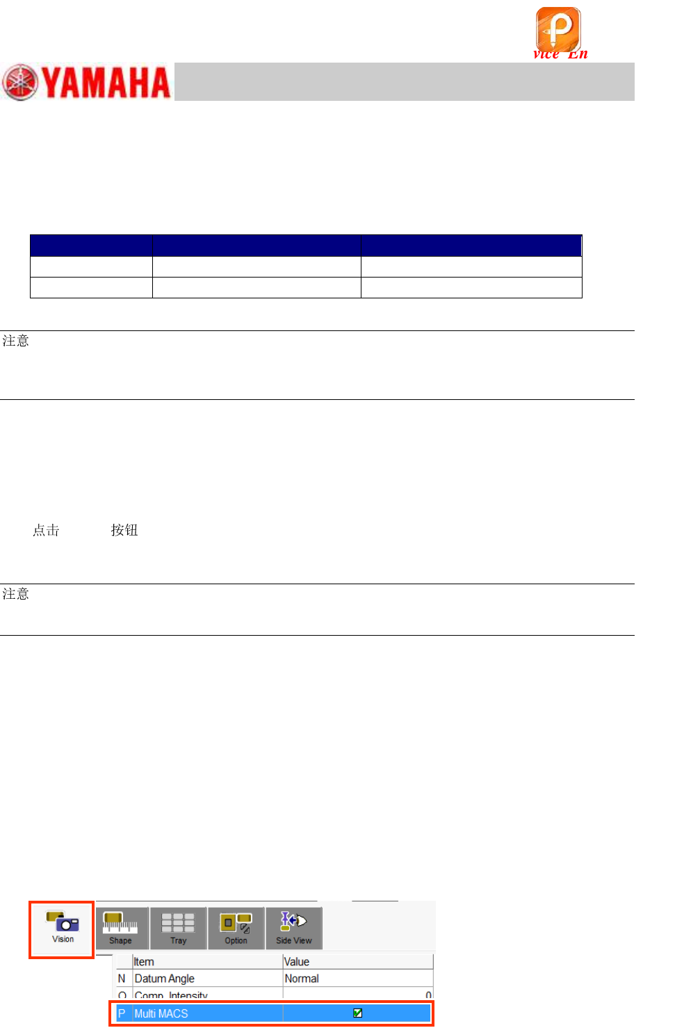
<“Multi MACS”>
When performing the ACP-Chip and the ACP-Station adjustments, the multi MACS is recognized
each time during the adjustment process. Make sure that the “Multi MACS” checkbox on the [Part]
– [Vision] window is ticked before performing the adjustment.
Figure 56
该文档是极速PDF编辑器生成,
如果想去掉该提示,请访问并下载:
http://www.jisupdfeditor.com/

For Service Engineer
Service Information
SI1610004E-000= YSM10_Procedures for the adjustments required after installing a machine
44/107
6. Make sure that the 1005 ceramic chip component on the board can be recognized
properly.
1) Leave the 1005 ceramic chip component attached to Head 1 (The component that recognition
check was done in step 5).
2) Trace one of the mounting coordinates of the board data by Head 1.
3) With the machine in the “Emergency Stop” state, lower Head 1 by hand and place the picked
up component on the sticky surface of the board.
4) Make sure that the 1005 ceramic component that was traced and attached to the board
surface can be recognized properly.
Use the mark information “No.11 CERA 1005” and perform the recognition test on the “Mark
Adjust” window.
(If the recognition cannot be performed properly, adjust the brightness on the “Mark Light”
window so that the component can easily be recognized.)
该文档是极速PDF编辑器生成,
如果想去掉该提示,请访问并下载:
http://www.jisupdfeditor.com/
For Service Engineer
Service Information
SI1610004E-000= YSM10_Procedures for the adjustments required after installing a machine
45/107
5.5 ACP-Chip accuracy adjustment
For YSM10, use the Scan camera as a main camera to perform the ACP-Chip adjustment first.
5.5.1 Start up the ACP-Chip utility and perform setting for the adjustment
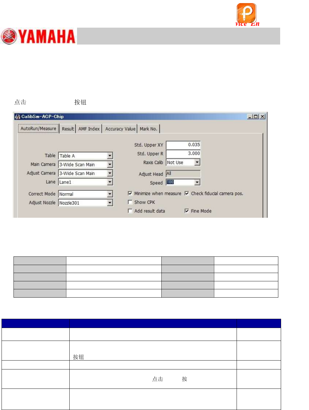
1. [026 ACP-Chip] on the CalibSm main menu.
Figure 57
2. Check the settings on the “AutoRun/Measure” tab.
The Scan camera (3-Scan Main)is the main camera of YSM10.
Make sure that all the settings are appropriate.
Table
Table A
Std. Upper XY
0.035
Main Camera
3-Scan Main
Std. Upper R
3.000
Adjust Camera
3-Scan Main
Raxis Calib
Not Use
Correct Mode
Normal
Speed
100
Adjust
301 (312)
Table 26
Settings for other functions
Name of the checkbox
Description
Default setting
Minimize when measure
The function minimizes the window at the time of the ACP-Chip
measurement.
Ticked
Check Fiducial camera
Pos.
The function checks the fiducial camera relative position before
performing the measurement by tapping the [All] or the [Measure]
.
Ticked
Show CPK
The measured result can be displayed in the CPK representation.
Not Ticked
Add result data
The function adds the measured results to the existing adjustment
result file. To display the file,
[Ref.] displayed when
the “Add result data” checkbox is ticked, and select the file.
Not Ticked
Fine Mode
Mode used when performing the ACP-Chip measurement. The
function enhances the performance in the measurement for the R
direction of the chip components.
Ticked
Table 27
[Items to be adjusted]
Fiducial camera position coordinate (XY)
All the heads of the main camera (Main ): “Precision Zigzag” parameter (X, Y)
All the heads except for Head 1 of the main camera (Main ): “Precision Parallel”
parameter (X, Y)
该文档是极速PDF编辑器生成,
如果想去掉该提示,请访问并下载:
http://www.jisupdfeditor.com/