YSM10安装调整(eng).pdf - 第62页
For Ser v ice E n gineer Service Information SI1610004E -000= YSM10_Proced ures for the adjustmen ts required after installing a machine 62/107 3. Check the XY coordin ates of the Lo cal fiducial and the mark nu mber. Us…
For Service Engineer
Service Information
SI1610004E-000= YSM10_Procedures for the adjustments required after installing a machine
61/107
6.6 Check the board data
Use some information of the board data “MCH_SETUP.ygx” to perform the “ACP-Station”
adjustment.
6.6.1 Information required for the adjustment
* The coordinates shown in this document are the default values.
Mounting coordinate X, Y
X, Y coordinates of “Board Offset” and “Block Offset”
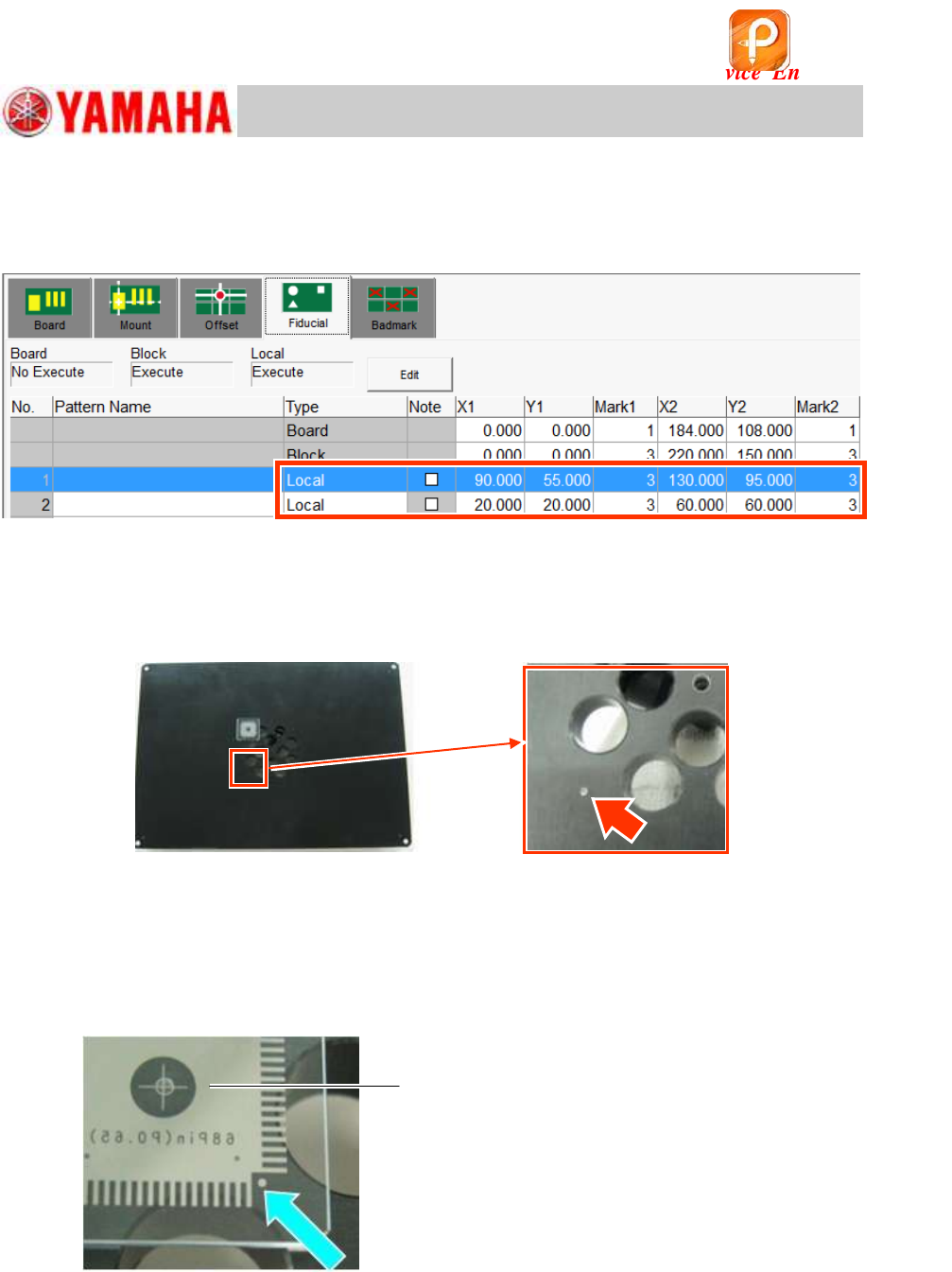
X, Y coordinates and Mark number of “Local” on the [Board]-[Fiducial] window
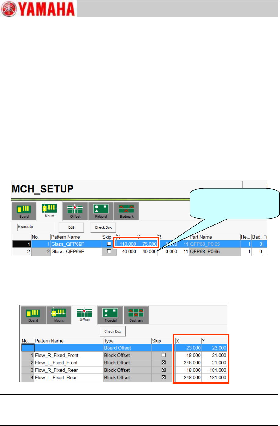
1. Check the mounting coordinate X, Y.
Use the X, Y coordinates of the mounting coordinate No.1 (on the “Mount” tab) as the coordinate
for mounting a component in the center of the station (Size: 240x170mm). When using a small
station (Size: 100x100) for the adjustment, use the coordinate No.2.
Do not change the X and Y coordinates.
The R coordinate and the Part number are not used here as they are set in the “ACP-Station”
utility.
Figure 80
2. Check the X, Y coordinates of “Board Offset” and “Block Offset”.
The coordinate of the block origin to be used varies depending on the conveyor specification of the
machine. Make sure that the block origin corresponds to the conveyor specification of the machine.
Set the same block origin number on the “ACP-Station” window in the adjustment utility.
Figure 81
Caution:
DO NOT change the “Board Offset” coordinate as it is used in other adjustment utilities.
If the block origin is off the position, check if the board is clamped properly, and the edge clamp
coordinate is appropriate.
When a small FAMF station is
used, select No.2.
Use “2” as the local fiducial.
For Service Engineer
Service Information
SI1610004E-000= YSM10_Procedures for the adjustments required after installing a machine
62/107
3. Check the XY coordinates of the Local fiducial and the mark number.
Use the coordinates of the local fiducial, and the mark number “3”.
Use the
1.0mm holes on the lower left and on the upper right on the station as the fiducial
marks.
Figure 82
4. Check if the fiducial mark can be recognized properly.
Make sure that the local fiducial mark can be recognized properly on the “Mark Adj” window.
Mark No.: Mark No.: No.3 “Hole_1.0_Circle/For_Station”
Figure 83
5. Check if the mark on the QFP can be recognized properly.
Place a QFP in the center of the FAMF station, and make sure that the
0.5mm marks of the
four (4) corners can be recognized properly.
(You can use either of the 68-pin QFP or the 208-pin QFP for the check.)
Mark No.: No.29 “QFP_0.5_Circle/4_Corners (Station)”
Figure 84
6. Make sure that the picked up QFP can be recognized properly.
Make the suck a 68-pin QFP, and make sure that the QFP can be recognized
properly.
Part No.: No.11 QFP68_P0.65/QFP_68Pin
Make sure to set the QFP so that the
printed side of it faces down.
该文档是极速PDF编辑器生成,
如果想去掉该提示,请访问并下载:
http://www.jisupdfeditor.com/
For Service Engineer
Service Information
SI1610004E-000= YSM10_Procedures for the adjustments required after installing a machine
63/107
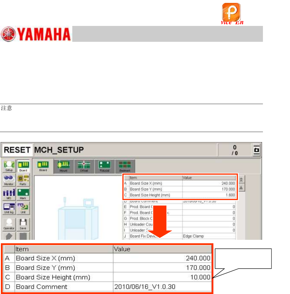
6.6.2 Change the “Board Size Height” to 10.0mm
Change the “Board Size Height” of the Board data “MCH_SETUP.ygx” before performing the
“ACP-Station” adjustment.
Board Size Height (mm): 1.6mm
10.0mm
:
The thickness of the station is 10.0mm. It is heavy with the air hose connected to it and may not be
secured properly just by the board clamp. (The station may tilt due to its own weight.)
Set the pushup pins under the 10.0mm thick part of the FAMF station in addition to the board clamp.
Figure 85
Change the setting
to “10.000”.
该文档是极速PDF编辑器生成,
如果想去掉该提示,请访问并下载:
http://www.jisupdfeditor.com/