YSM10安装调整(eng).pdf - 第75页
For Ser v ice E n gineer Service Information SI1610004E -000= YSM10_Proced ures for the adjustmen ts required after installing a machine 75/107 6.9.4 “Feedback l o g ” confirm ation window If y ou select “Feedback log, y…
For Service Engineer
Service Information
SI1610004E-000= YSM10_Procedures for the adjustments required after installing a machine
74/107
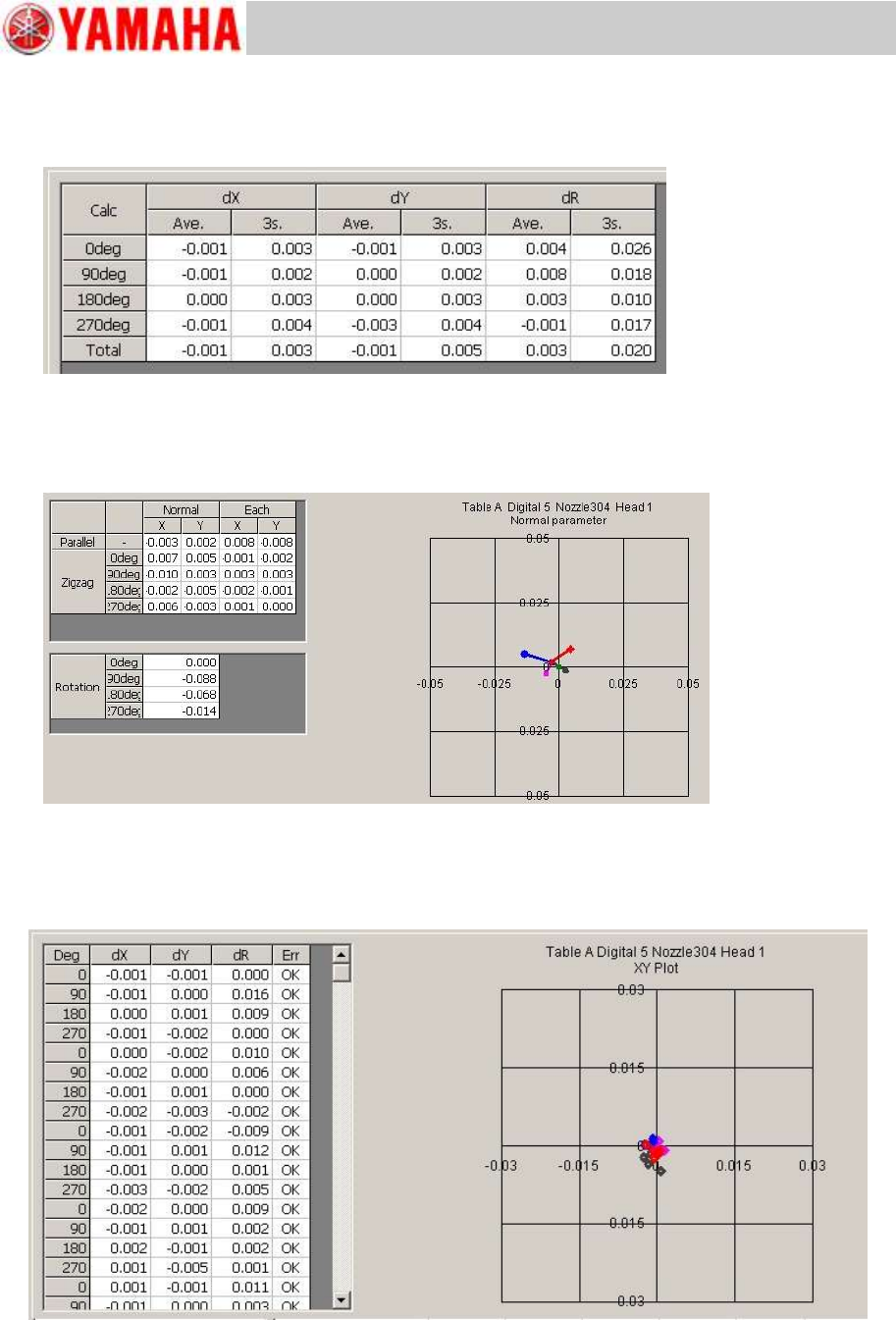
“Calc” tab
The detailed information of the mounting result for each adjustment can be checked.
Figure 106
“Precision”
The parameter calibration information for each adjustment result can be checked.
Figure 107
“Result” tab
The mounting result after the adjustment for each result can be checked on the graph.
Figure 108
For Service Engineer
Service Information
SI1610004E-000= YSM10_Procedures for the adjustments required after installing a machine
75/107
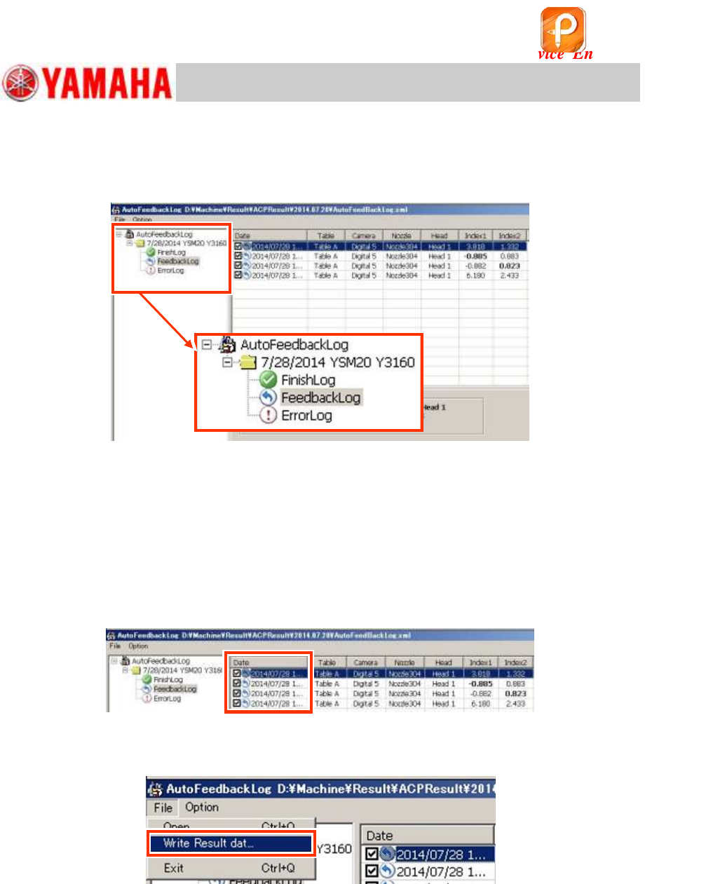
6.9.4 “Feedback log” confirmation window
If you select “Feedbacklog, you can check the record that the feedback has been performed during
the adjustment.
Figure 109
6.9.5 Export the accuracy data “Result.dat” before the adjustment
When printing out the accuracy data before the adjustment (before maintenance) on the VgChart,
export the “Result.dat” file from the “Feedback Log” and create the graph on other PC.
The oldest data of the adjustment date in the “Feedback Log” is the accuracy data for each
and head before the adjustment.
1. Select the file to export.
Tick the “Date” checkbox of the file to be exported.
Figure 110
2. Export the file.
Select “Write Result data” from the “File” pull-down menu.
Figure 111
3. Select the destination to save the file.
The file is saved as the name “Result.dat” file in the specified destination.
6.9.6 “Error Log” confirmation window
If the adjustment cannot be completed properly, the log is saved. Mainly when the repeatability of
the mounting operation is poor, the adjustment is interrupted and the precision parameter, the
mounting result, Index and so on at the time of interruption is recorded. Identify the cause of the
problem, take appropriate measures and perform the adjustment again.
该文档是极速PDF编辑器生成,
如果想去掉该提示,请访问并下载:
http://www.jisupdfeditor.com/
For Service Engineer
Service Information
SI1610004E-000= YSM10_Procedures for the adjustments required after installing a machine
76/107
7. Items to be checked after performing the accuracy adjustment
7.1 Check the Edge clamp position
Place a board on the mounting position and secure it. Set the X and Y coordinates of “Board
Offset” to 0.00 and move the camera to the position by tapping the [Trace]
.
7.2 “FeederPos”
7.2.1 Feeder pickup position XY adjustment
Measure the X and Y coordinates of the reference feeder specified per section.
Basically, the fiducial camera is used for performing the measurement. When the camera cannot
be moved to the reference feeder position, change the “Tool Set No” and measure other feeder
position.
When using a Pickup position adjustment jig, enter the correction values (Offset value) of the jig
labeled on the jig into the “Tool Offset X, Y, Z” fields.
1. Read the board data “MCH_SETUP”.
Use the board information No.8 of the board data to recognize the mark on the jig and check the
position shift.
When performing the adjustment without reading the board data “MCH_SETUP”, create the mark
information and set the number of newly created information to “Mark No.”.
<Mark information of the feeder master jig>
MarkType
Fiducial
Shape Type
Circle
Mark Out Size (mm)
2.0mm
Surface Type
NonReflect
Table 37
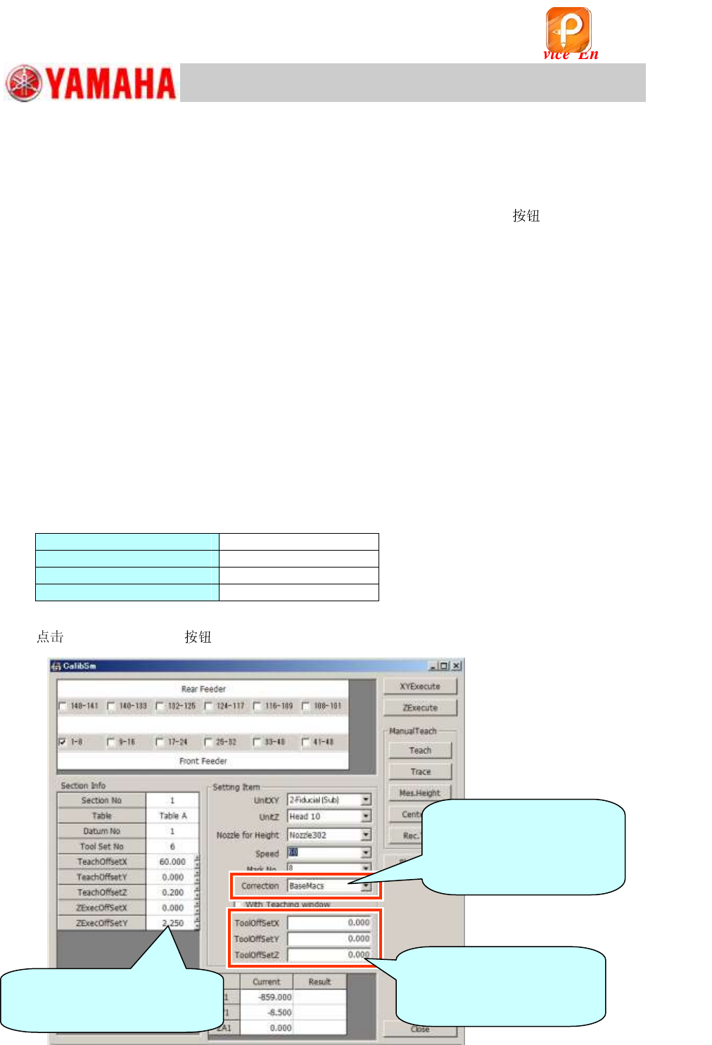
2. [005 Feeder Pos] on the CalibSm main menu.
Figure 112
Before performing the adjustment,
make sure that the value of
“ZExecOffsetY” is set to “2 .250”.
[Important]
Make sure to enter the
correction value (Offset value)
of the jig before the adjustment.
[Correction]
Select “BaseMACS” when
“BaseMACS” correction needs
to be performed for adjusting
the pickup position.
该文档是极速PDF编辑器生成,
如果想去掉该提示,请访问并下载:
http://www.jisupdfeditor.com/