YSM10安装调整(eng).pdf - 第97页
For Ser v ice E n gineer Service Information SI1610004E -000= YSM10_Proced ures for the adjustmen ts required after installing a machine 97/107 3. Shift the 16-pin QF P 1.5mm to 2.0mm and m ake the suck the �…
For Service Engineer
Service Information
SI1610004E-000= YSM10_Procedures for the adjustments required after installing a machine
96/107
11.3.4 Scan camera -“” adjustment
The Scan camera is the main component recognition camera for YSM10.
・ Required : Type 303A (314A) (For SOP)
・ Required component: 16-pin QFP (with a sticker on the back) / KHY-M880A-00
16-pin QFP
Part No. (MCH_SETUP)
WITHOUT a sticker
(KW8-M880A-00 / QFP 16P)
No.10 (QFP16_P0.8)
Use either of
the QFP
WITH a sticker
(KHY-M880A-00 /
QFP 16P ASSY)
No.34 (QFP16_P0.8_WHITE)
Table 43
1.
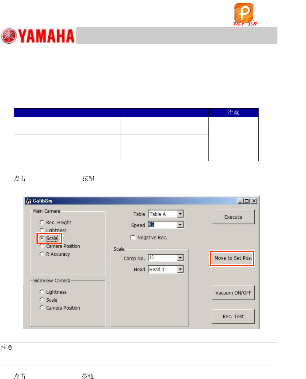
[010 Scan camera] on the CalibSm main menu and select “” from
“Main Camera”.
Figure 141
:
When the 16-pin QFP with a white sticker on the back of it is used for the adjustment, make sure
to tick the “Negative Rec.” checkbox.
2.
[Move to Set Pos.] .
If the machine is equipped with an ANC:
The of the head to be adjusted is changed to 303A (314A) automatically and the
head moves to above the front-side feeder bank.
If the machine is NOT equipped with an ANC:
The head moves to above the front-side feeder bank. Put the machine into the “Emergency
Stop” state and attach the 303A (314A) to the head by hand.
该文档是极速PDF编辑器生成,
如果想去掉该提示,请访问并下载:
http://www.jisupdfeditor.com/
For Service Engineer
Service Information
SI1610004E-000= YSM10_Procedures for the adjustments required after installing a machine
97/107
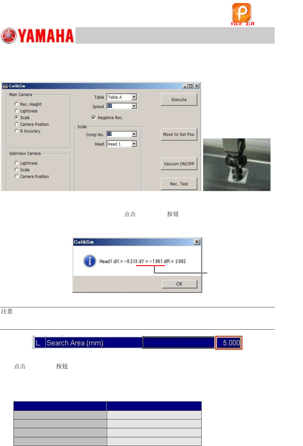
3. Shift the 16-pin QFP 1.5mm to 2.0mm and make the suck the QFP.
Shift the 16-pin QFP from the center 1.5 to 2.0mm to the Y-direction (the direction of
the leaf spring) when setting it to the tip.
Figure 142
4. Perform the recognition test.
After attaching the QFP to the ,
[Rec.Test] to perform the recognition
test, and check if the shift amount of the result is within 1.5mm to 2.0mm.
If the shift amount is less than 1.5mm, set the QFP again.
Figure 143
:
If a recognition error occurs, change the setting of the “Search Area (mm)” of the Part information
“No.10 QFP16_P0.8” and “No.34 QFP16_P0.8_WHITE” to 5.0mm on the [Parts] – [Vision] window.
Figure 144
5.
[Execute] to start the adjustment.
6. Save the measured data.
Make sure that the measured values fall within the specification and save the
data.
<Specified value>
Item
Specified value
Camera Angle
0.000 +/- 0.500 degrees
X
26.000
m
Y
25.500 ~ 26.500
m
Dual Rec Offset
-0.052 ~ 0.052 mm
Table 44
The value of “dY” should
fall within 1.5 to 2.0.
该文档是极速PDF编辑器生成,
如果想去掉该提示,请访问并下载:
http://www.jisupdfeditor.com/
For Service Engineer
Service Information
SI1610004E-000= YSM10_Procedures for the adjustments required after installing a machine
98/107
11.3.5 “Head Offset Z” adjustment
:
Make sure to adjust the “Vacuum level” adjustment before performing the “Head Offset Z” adjustment.
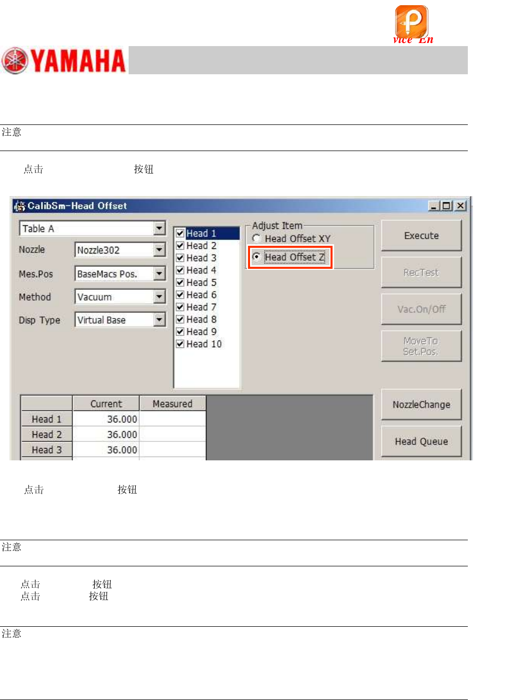
1. [015 Head Offset] on the CalibSm main menu and select “Head Offset Z”
from “Adjust Item”.
Figure 145
2. [ Change] to change the to the Type 302A (313A) .
If the machine is not equipped with an ANC, change the s by hand.
3. Make sure that “BaseMacs Pos.” is selected from the “Mes.Pos” pull-down menu.
:
As the Virtual origin is used for YSM10, the reference positon for the Head Offset Z is the BaseMACS.
4.
[Execute] .
[Execute] to start the adjustment. Make sure that the measured value is appropriate,
and save the data.
:
After performing the “Head Offset Z” adjustment, make sure to perform the “PCB Height” adjustment.
This is because both the “Head Offset Z” and the “PCB Height” is adjusted in reference to the virtual
origin, and the coordinates of the “PCB Height” may be changed by adjusting the Head Offset Z, which
may affect the mounting accuracy.
See “11.3.6 “PCB Height” adjustment” for the method.
该文档是极速PDF编辑器生成,
如果想去掉该提示,请访问并下载:
http://www.jisupdfeditor.com/