YSM10安装调整(eng).pdf - 第99页
For Ser v ice E n gineer Service Information SI1610004E -000= YSM10_Proced ures for the adjustmen ts required after installing a machine 99/107 11.3.6 “ PCB He ight ” adjustm ent The four (4) points on the upper surf ace…
For Service Engineer
Service Information
SI1610004E-000= YSM10_Procedures for the adjustments required after installing a machine
98/107
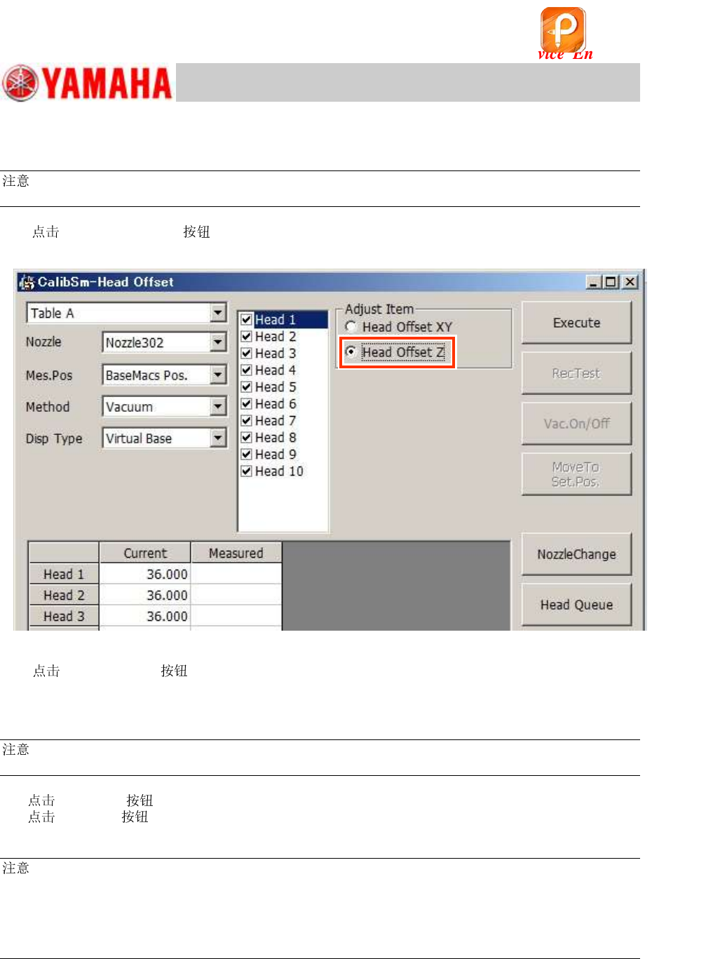
11.3.5 “Head Offset Z” adjustment
:
Make sure to adjust the “Vacuum level” adjustment before performing the “Head Offset Z” adjustment.
1. [015 Head Offset] on the CalibSm main menu and select “Head Offset Z”
from “Adjust Item”.
Figure 145
2. [ Change] to change the to the Type 302A (313A) .
If the machine is not equipped with an ANC, change the s by hand.
3. Make sure that “BaseMacs Pos.” is selected from the “Mes.Pos” pull-down menu.
:
As the Virtual origin is used for YSM10, the reference positon for the Head Offset Z is the BaseMACS.
4.
[Execute] .
[Execute] to start the adjustment. Make sure that the measured value is appropriate,
and save the data.
:
After performing the “Head Offset Z” adjustment, make sure to perform the “PCB Height” adjustment.
This is because both the “Head Offset Z” and the “PCB Height” is adjusted in reference to the virtual
origin, and the coordinates of the “PCB Height” may be changed by adjusting the Head Offset Z, which
may affect the mounting accuracy.
See “11.3.6 “PCB Height” adjustment” for the method.
该文档是极速PDF编辑器生成,
如果想去掉该提示,请访问并下载:
http://www.jisupdfeditor.com/
For Service Engineer
Service Information
SI1610004E-000= YSM10_Procedures for the adjustments required after installing a machine
99/107
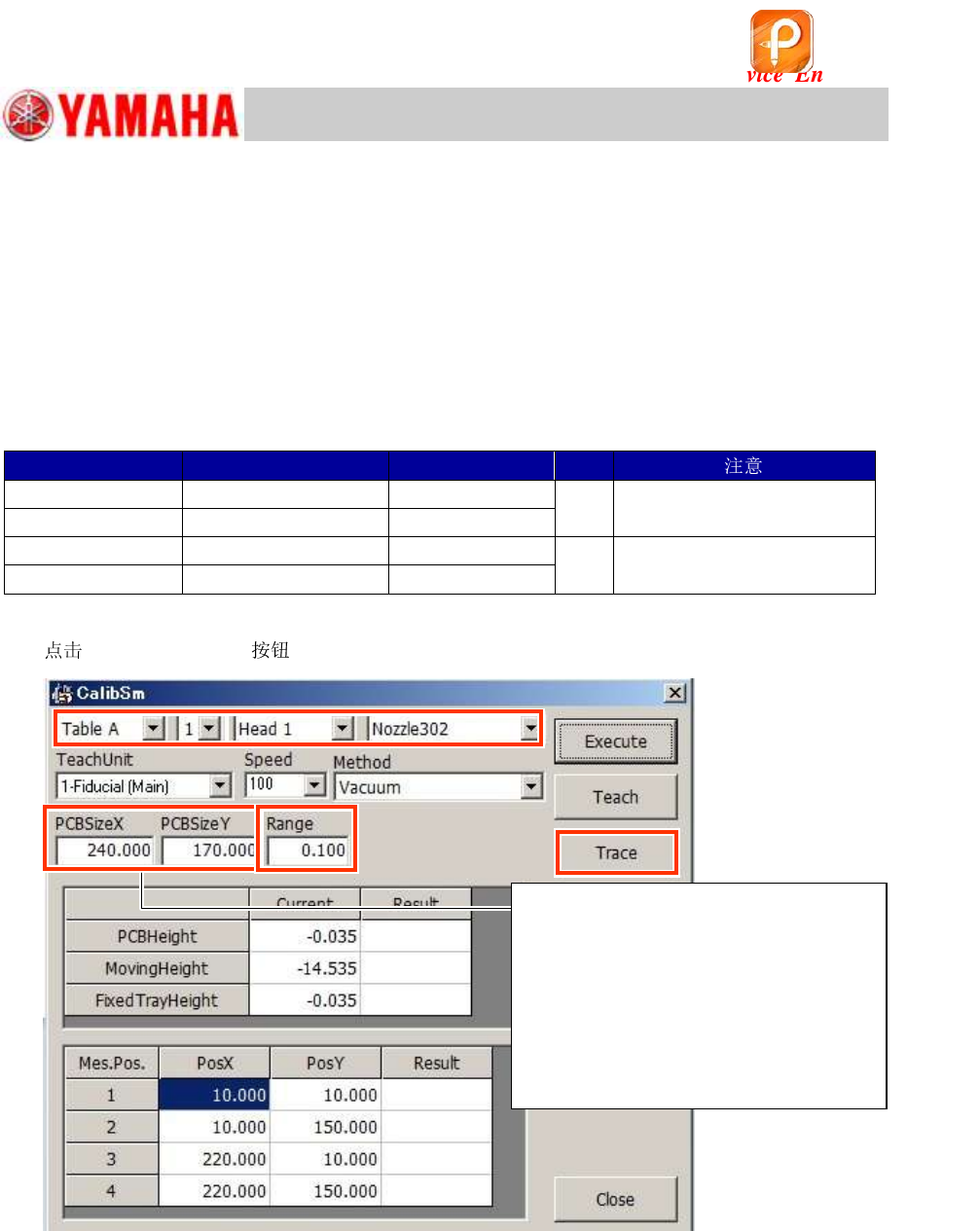
11.3.6 “PCB Height” adjustment
The four (4) points on the upper surface of the aluminum frame of the board is measured,
and the height of the lowest point of the four (4) is saved as the “PCB height”.
The “PCB height” is the reference height for the head to mount components, and is automatically
measured according to the changes in the vacuum pressure of the when it contacts the
board surface.
The “Pick Level“ and the “Mount Level” adjustments need to be completed before measuring the
PCB height.
Required jigs
Part No.
Part Name
Jig
Qty
ACP board
PCB ASSY.4
KM0-M8810-40
1
Select either of the boards.
AMF board
PCB ASSY.1
KM0-M8810-10
Type 302A
302A ASSY.
KHN-M7720-A0
1
Select either of the s.
Type 313A
313A ASSY.
KHY-M7730-A0
Table 45
1.
[006 PCB Height] on the CalibSm main menu.
Figure 146
2. Check the used for the measurement.
Select “ 302A” or “ 313A” as the PCB height is measured by the difference in the
vacuum pressure of the .
If the machine is not equipped with an ANC, attach the to the head by hand.
3. Check the value in the “Range” field.
Make sure that the value in the “Range” field (specified value) is “0.100”.
The four (4) points on the aluminum frame of the board are measured and the difference
between the maximum and the minimum values is checked automatically.
Step 3
“PCB Size X, Y” are the reference
values for the measurement point of
the PCB height.
When the board size is changed, the
coordinate of the measurement point
is changed automatically.
(It works the same for the machine
whose board flow direction is from left
to right.)
Step 2
该文档是极速PDF编辑器生成,
如果想去掉该提示,请访问并下载:
http://www.jisupdfeditor.com/
For Service Engineer
Service Information
SI1610004E-000= YSM10_Procedures for the adjustments required after installing a machine
100/107
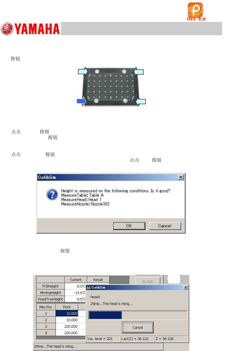
4. Set the board on the conveyor.
Set the board on the conveyor and clamp it by tapping the [Main stopper] and the [Fix Pcb]
s.
Figure 147
5. Select “Head 1” from “Teach Unit”.
6. [Trace] and move the head.
After tapping the
, put the machine into the “Emergency Stop” state and lower Head 1 by
hand to make sure that the position when it descends is appropriate (at the lower left of the
aluminum frame of the board).
7.
[Execute] .
When the dialog box appears, check the message and [OK] .
Figure 148
<When the [Execute]
is tapped…>
The four (4) points on the top surface of the aluminum frame are measured, and the height of
the lowest point is saved as the “PCB height” automatically.
Figure 149
该文档是极速PDF编辑器生成,
如果想去掉该提示,请访问并下载:
http://www.jisupdfeditor.com/