00190702-04.pdf - 第18页
Retrofitt ing Instructi ons Bulk-Case Feeders Retrofitt ing Instruct ions Edition 04/96 Page 18 of 23 2 W ork to Be Carried Out 2.1 BC Compressed Air S upply (Change-Over Table) • Install the req uired line computer , st…

Retrofitting Instructions Retrofitting Instructions Bulk-Case Feeders
Edition 05/99
Page 17 of 23
1.4 Safety Information
Danger !!!
The machines of the SIPLACE family are supplied with line voltage of 3 x 400V
10%, 50/60 Hz. Parts of
this system therefore carry dangerous voltages even when switched off at the main switch.
Improper handling of these machines can therefore lead to death, serious injury and considerable damage to
property.
Note the valid accident prevention and any other relevant regulations (in particular EN 60204).
Only qualified and adequately trained personnel may carry out this retrofitting work.
Switch the machine off at the main switch before beginning retrofitting work, and disconnect the power plug.
Secure the system so that it cannot be switched on again.
If you do not comply with the above, contact with live parts can result in death or serious injury.
1.4.1 Definitions
Qualified and adequately trained personnel:
Persons who know how to install, operate and maintain the placement machine and the optional devices and
who have relevant qualifications, such as:
•
Training or instruction in switching circuits and unit components on and off, and isolating, grounding or
identifying them in accordance with the standards of safety systems, as well as the authorization to do
so
•
Training or instruction in the maintenance and use of appropriate safety equipment in accordance with
safety system standards
•
Training in first aid
Retrofitting Instructions Bulk-Case Feeders Retrofitting Instructions
Edition 04/96
Page 18 of 23
2 Work to Be Carried Out
2.1 BC Compressed Air Supply (Change-Over Table)
•
Install the required line computer, station computer and component change-over table software, if
necessary.
•
Replace the pressure regulator with the ring in the pneumatic unit (figure 3).
•
Remove the feeders from the component change-over table.
•
Place the compressed-air distributor on the removed front edge of the component change-over table
(figure 1).
•
In order to center the left-hand side of the compressed-air distributor, place adjustment gage 1 on
track 1 of the component table plate.
•
In order to center the right-hand side of the compressed-air distributor, place adjustment gage 2 on
track 115 of the component table plate.
•
Secure the compressed-air distributor with 3 M8x20 Allen screws on the component change-over
table.
•
Adjust the front strip on the compressed-air distributor to the lower edge of the feeders.
•
On the component change-over table (figure 1), replace the existing bracket with the controller and
cable mount.
•
Establish the pneumatic connection from the pressure regulator to the compressed-air distributor
and the Siplace compressed-air connection.
•
Use the pressure regulator to set operating pressure of 2 bar.
2.2 Bulk-Case Compressed-Air Supply (Short)
•
Install the required line computer, station computer and component change-over table software, if
necessary.
•
Replace the pressure regulator with the ring in the pneumatic unit (figure 3).
•
Remove the feeders from the component change-over table.
•
Place the compressed-air distributor on the removed front edge of the component change-over table
(figure 1).
• In order to center the left-hand side of the compressed-air distributor, place adjustment gage 1 on
track 59 of the component table plate.
• In order to center the right-hand side of the compressed-air distributor, place adjustment gage 2 on
track 115 of the component table plate.
• Secure the compressed-air distributor with 3 M8x20 Allen screws on the component change-over
table.
• Adjust the front strip on the compressed-air distributor to the lower edge of the feeders.
• On the component change-over table (figure 1), replace the existing bracket with the controller and
cable mount.
• Establish the pneumatic connection from the pressure regulator to the compressed-air distributor
and the Siplace compressed-air connection.
• Use the pressure regulator to set operating pressure of 2 bar.
Retrofitting Instructions Retrofitting Instructions Bulk-Case Feeders
Edition 05/99
Page 19 of 23
2.3 Retrofit Kit, Bulk-Case Air Supply (Change-Over Table)
•
Replace the pressure regulator with the ring in the pneumatic unit (figure 3).
•
On the component change-over table (figure 1), replace the existing bracket with the controller and
cable mount.
•
Establish the pneumatic connection from the pressure regulator to the compressed-air distributor
and the Siplace compressed-air connection.
•
Use the pressure regulator to set operating pressure of 2 bar.
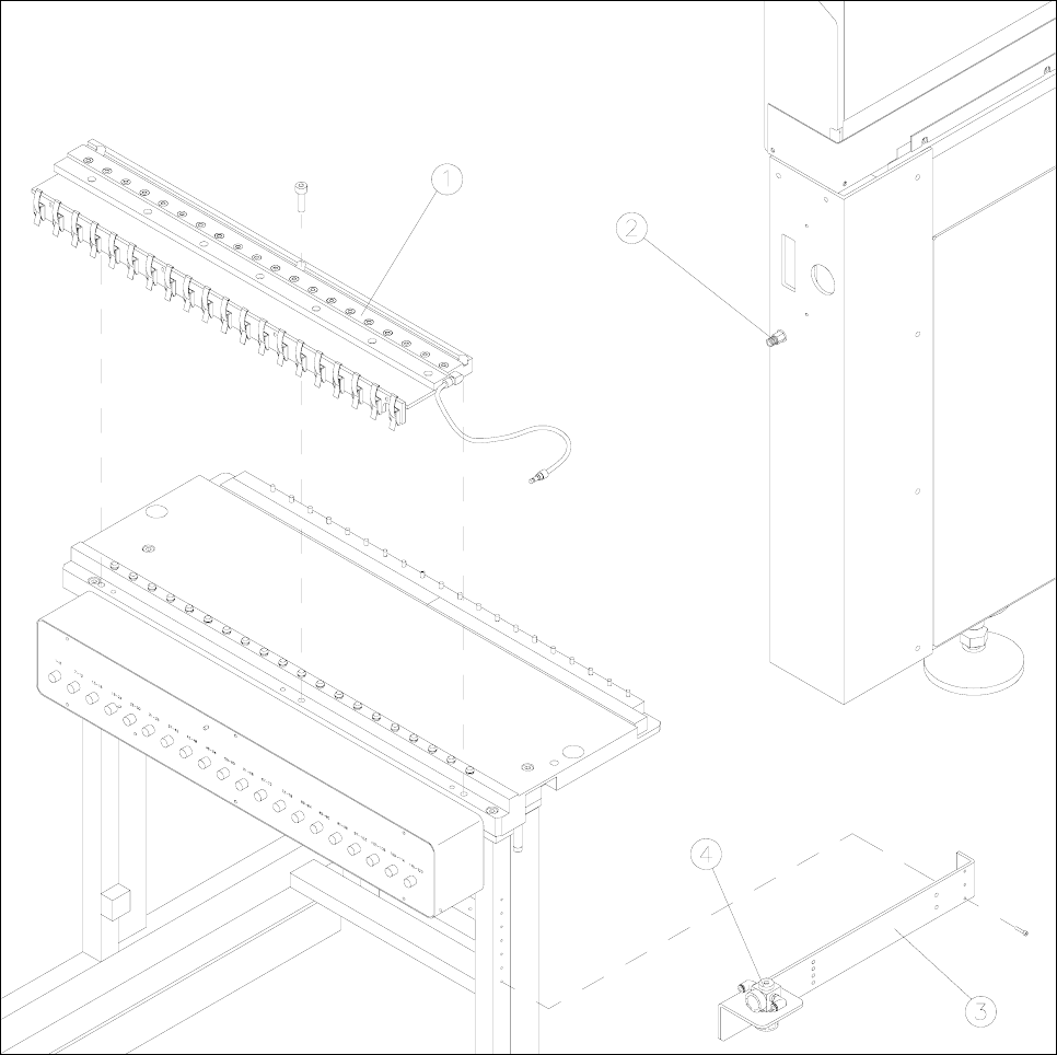
Figure 1 Component change-over table with compressed-air distributor and pressure regulator
Key to figure 1
1) Compressed-air distributor 2) Siplace compressed-air connection
3) Controller and cable mount 4) Pressure regulator