00190702-04.pdf - 第20页
Retrofitt ing Instructi ons Bulk-Case Feeders Retrofitt ing Instruct ions Edition 04/96 Page 20 of 23 2.4 BC Air Supply (Moving Change-Over Table) • Install the req uired line computer , station com puter and comp onent …
Retrofitting Instructions Retrofitting Instructions Bulk-Case Feeders
Edition 05/99
Page 19 of 23
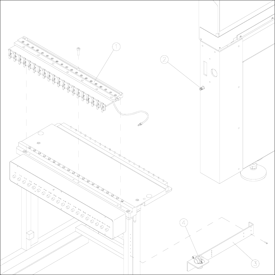
2.3 Retrofit Kit, Bulk-Case Air Supply (Change-Over Table)
•
Replace the pressure regulator with the ring in the pneumatic unit (figure 3).
•
On the component change-over table (figure 1), replace the existing bracket with the controller and
cable mount.
•
Establish the pneumatic connection from the pressure regulator to the compressed-air distributor
and the Siplace compressed-air connection.
•
Use the pressure regulator to set operating pressure of 2 bar.
Figure 1 Component change-over table with compressed-air distributor and pressure regulator
Key to figure 1
1) Compressed-air distributor 2) Siplace compressed-air connection
3) Controller and cable mount 4) Pressure regulator
Retrofitting Instructions Bulk-Case Feeders Retrofitting Instructions
Edition 04/96
Page 20 of 23
2.4 BC Air Supply (Moving Change-Over Table)
•
Install the required line computer, station computer and component change-over trolley software, if
necessary.
•
Replace the pressure regulator with the ring in the pneumatic unit (figure 3).
•
Remove the feeders from the component change-over trolley.
•
Place the compressed-air distributor on the removed front edge of the component change-over
trolley (figure 2).
•
In order to center the left-hand side of the compressed-air distributor, place adjustment gage 1 on
track 1 of the component table plate.
•
In order to center the right-hand side of the compressed-air distributor, place adjustment gage 2 on
track 115 of the component table plate.
•
Secure the compressed-air distributor with 3 M8x20 Allen screws on the component change-over
trolley.
•
Adjust the front strip on the compressed-air distributor to the lower edge of the feeders.
•
On the component change-over trolley (figure 2), replace the existing bracket with the controller and
cable mount.
•
Establish the pneumatic connection from the pressure regulator to the compressed-air distributor
and the change-over trolley.
•
Use the pressure regulator to set operating pressure of 2 bar.
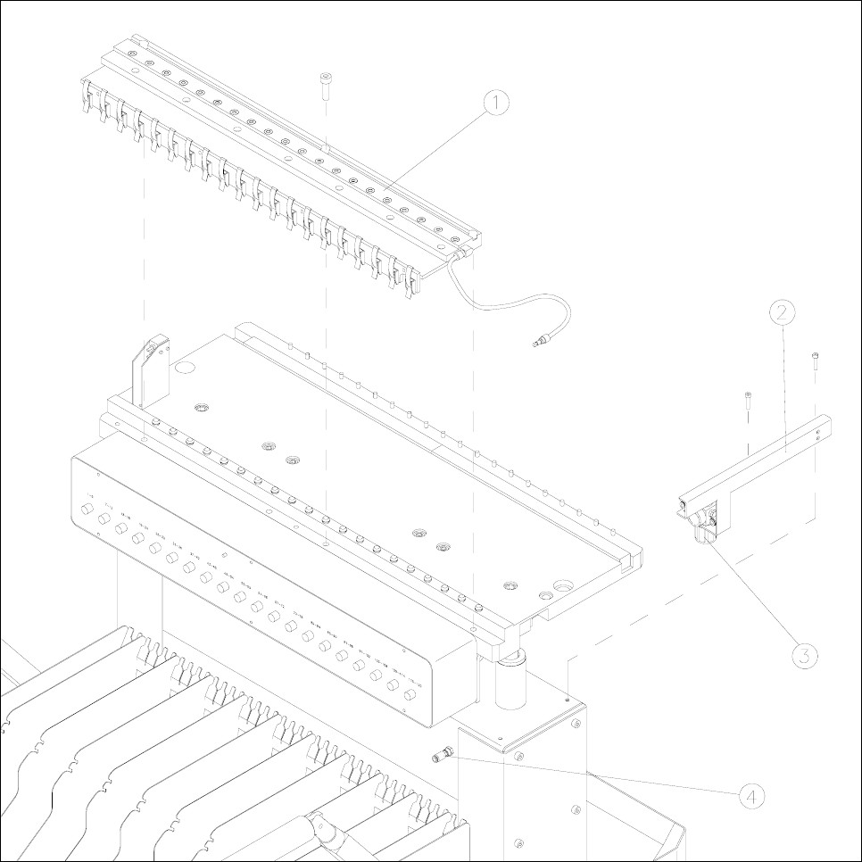
2.5 Retrofit Kit, Bulk-Case Air Supply (Change-Over Trolley)
•
Replace the pressure regulator with the ring in the pneumatic unit (figure 3).
•
On the component change-over trolley (figure 2), replace the existing bracket with the controller and
cable mount.
•
Establish the pneumatic connection from the pressure regulator to the compressed-air distributor
and the change-over trolley.
•
Use the pressure regulator to set operating pressure of 2 bar.
Retrofitting Instructions Retrofitting Instructions Bulk-Case Feeders
Edition 05/99
Page 21 of 23
Figure 2 Component change-over trolley with compressed-air distributor and pressure regulator
Key to figure 2
1) Compressed-air distributor 2) Controller and cable mount
3) Pressure regulator 4) Compressed-air connection on the change-over trolley