00190702-04.pdf - 第22页
Retrofitt ing Instructi ons Bulk-Case Feeders Retrofitt ing Instruct ions Edition 04/96 Page 22 of 23 Figure 3 Pneumatic unit X100 Key to fig ure 3 1) Press ure regula tor, t o be repl aced w ith 2) R ing
Retrofitting Instructions Retrofitting Instructions Bulk-Case Feeders
Edition 05/99
Page 21 of 23
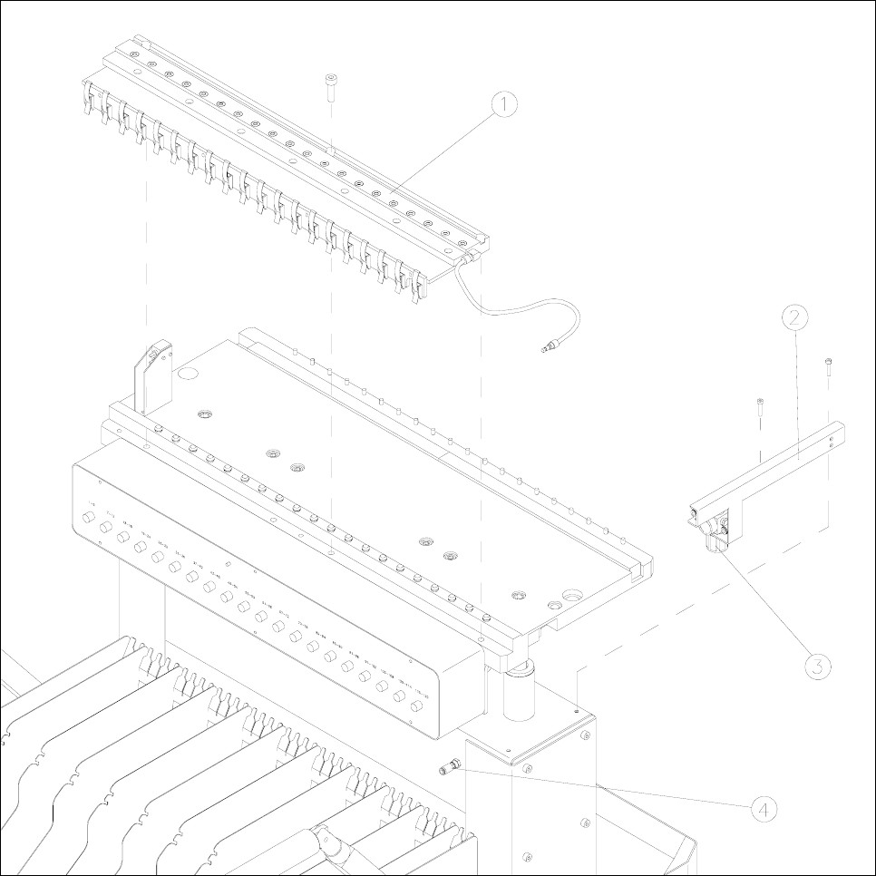
Figure 2 Component change-over trolley with compressed-air distributor and pressure regulator
Key to figure 2
1) Compressed-air distributor 2) Controller and cable mount
3) Pressure regulator 4) Compressed-air connection on the change-over trolley
Retrofitting Instructions Bulk-Case Feeders Retrofitting Instructions
Edition 04/96
Page 22 of 23
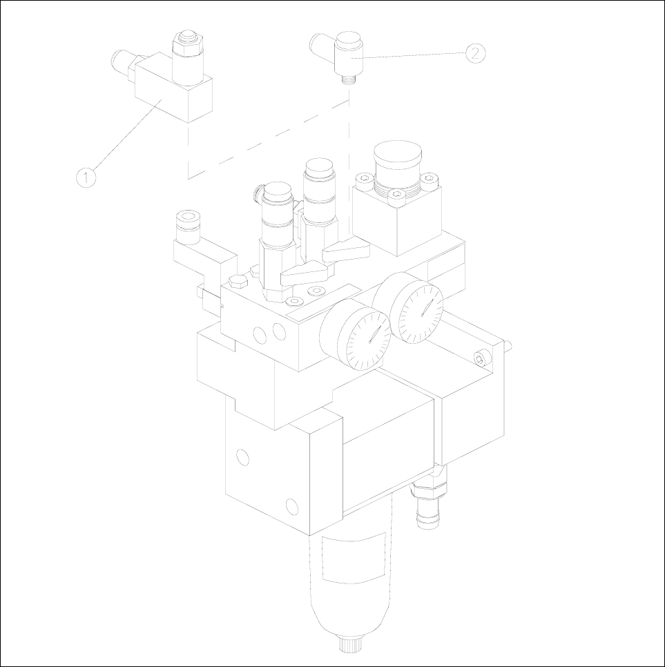
Figure 3 Pneumatic unit X100
Key to figure 3
1) Pressure regulator, to be replaced with 2) Ring
Retrofitting Instructions Retrofitting Instructions Bulk-Case Feeders
Edition 05/99
Page 23 of 23
2.6 Protection Conversion on SIPLACE 80 F3
•
Entirely remove the hinged doors with mounting from the left-hand placement side in the direction of
feed.
•
Use a countersink to sink the fixing holes of the strips in the machine frame.
•
Install the strips on the left- and right-hand side of the machine frame with 4 M4x10 countersunk screws
in each case.
•
Install the new hinged doors on the strips in the fixing holes provided.
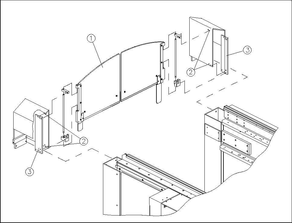
Figure 4 Hinged doors and fixing strips
Key to figure 4
1) Hinged doors with mounting
2) Fixing holes of the strips in the machine frame
3) Strips for fixing the hinged doors