YSi-V_Ope_E - 第100页
A-1 Appendix 1. Power connection terminals n Power supply specifications Model No. YSi-V Power 3-phase AC 200/208/220/240/380/400/416V (±10%) Frequency 50/60Hz Power capacity 7.0 kV A n Power input terminal T he power co…

Contents
1. Power connection terminals A-1
2. Connection between machines A-2
3. UPS (Uninterruptible Power Supply) A-3
3.1 Safety precaution A-3
3.1.1 Precautions when shipping or exporting the UPS A-3
3.1.2 Disposing of used battery after replacement A-3
3.1.3 Safety precautions A-3
3.2 About the UPS A-5
3.3 Operation and setting A-6
3.3.1 Front panel A-6
3.3.2 Operation during normal operation (power is normal) A-6
3.3.3 Operation during power failure or trouble A-6
3.4 Maintenance A-7
3.4.1 Battery replacement period A-7
3.4.2 Battery replacement A-7
3.4.3 Replacement battery storage A-7
3.5 Troubleshooting A-8
Appendix
A-1
Appendix
1. Power connection terminals
n
Power supply specifications
Model No. YSi-V
Power 3-phase AC 200/208/220/240/380/400/416V (±10%)
Frequency 50/60Hz
Power capacity 7.0 kVA
n
Power input terminal
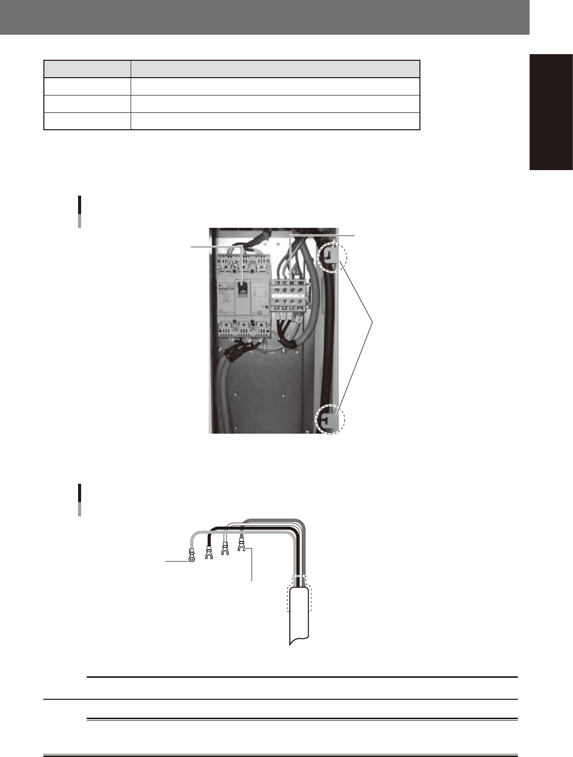
The power connection terminals are located behind the lower right panel on the front of the machine. Connect the power
cable leads as shown below to the L1, L2, L3, and earth (PE) on the power terminal block.
Main breaker
Power input terminal
YSi-V
Power input terminal (L1, L2, L3),
Earth terminal (PE)
Clamped at these
two positions
23500-M9-00
n
Power cable example
Power cable example
Fork tongue terminal
Ring tongue terminal
L1
L2
L3
PE
L=350mm
23501-M9-00
c
CAUTION
Use a power cable whose conductor cross-section area is greater than 3.3mm
2
(AWG12).
w
WARNING
TO AVOID THE RISK OF ELECTRICAL SHOCK, MAKE SURE THAT THE POWER SOURCE IS OFF BEFORE CONNECTING THE
POWER CABLE. ALSO MAKE SURE THAT THE GROUND CABLE IS SECURELY CONNECTED TO THE MACHINE.
A-2
Appendix
2. Connection between machines
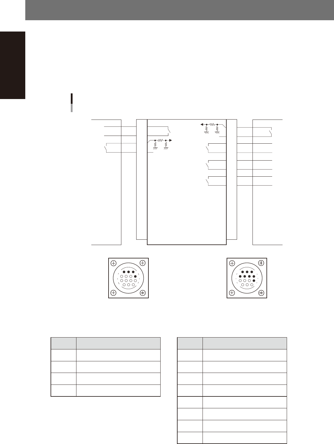
This inspection machine unloads a board when it receives a conveyance permission signal from the next
process machine, and then sends a conveyance permission signal to the previous process machine to request
another board.
The interface connector labeled "NEXT INTERFACE" connects to the next process machine (downstream
machine), and the interface connector labeled "PREVIOUS INTERFACE" connects to the previous process
machine (upstream machine). Both connectors are AMP 206043-1 (14-pin receptacle).
Each connector is installed inside the left and right cover on the lower rear of the machine. For the dual lane,
the connector is provided at two locations of each lane. The connectors are classified into lane 1 and lane 2.
14
11
12
7
4
8
3
1
7
12
4
8
1
14
11
3
Machine-to-machine connection example
1
2
3
4
5
6
7
8
9
10
11
12
13
14
1
2
3
4
5
6
7
8
9
10
11
12
13
14
Preceding process machine Next process machineThis machine
DC +24V
DC +24V
Relay output
Input
Input
Input
Input
Relay output
PNP input
PNP input
NEXT INTERFACE connector
AMP 206043-1
(14-pin receptacle)
PREVIOUS INTERFACE connector
AMP 206043-1
(14-pin receptacle)
23504-M9-00
n
Board transfer signal specifications
· PREVIOUS INTERFACE · NEXT INTERFACE
Pin No. Signal specifications Pin No. Signal specifications
1 Board transfer permit 1 Board transfer permit
2 Board transfer permit COM 2 Board transfer permit COM
3 Board transfer request 3 Board transfer request
4 Board transfer request COM 4 Board transfer request COM
5 Inspection result OK (pass)
6 Inspection result OK (pass) COM
7 Inspection result NG (fail)
8 Inspection result NG (fail) COM