YSi-V_Ope_E - 第101页
A-2 Appendix 2. Connection between machines This inspection machine unloads a board when it receives a conveyance permission signal from the next process machine, and then sends a conveyance permission signal to the prev…
A-1
Appendix
1. Power connection terminals
n
Power supply specifications
Model No. YSi-V
Power 3-phase AC 200/208/220/240/380/400/416V (±10%)
Frequency 50/60Hz
Power capacity 7.0 kVA
n
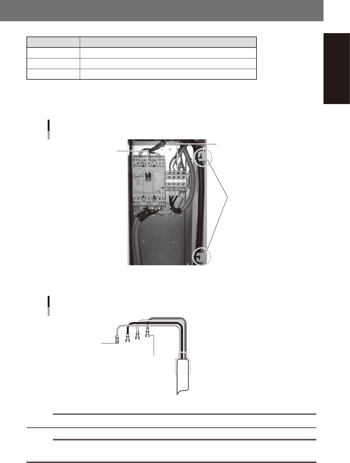
Power input terminal
The power connection terminals are located behind the lower right panel on the front of the machine. Connect the power
cable leads as shown below to the L1, L2, L3, and earth (PE) on the power terminal block.
Main breaker
Power input terminal
YSi-V
Power input terminal (L1, L2, L3),
Earth terminal (PE)
Clamped at these
two positions
23500-M9-00
n
Power cable example
Power cable example
Fork tongue terminal
Ring tongue terminal
L1
L2
L3
PE
L=350mm
23501-M9-00
c
CAUTION
Use a power cable whose conductor cross-section area is greater than 3.3mm
2
(AWG12).
w
WARNING
TO AVOID THE RISK OF ELECTRICAL SHOCK, MAKE SURE THAT THE POWER SOURCE IS OFF BEFORE CONNECTING THE
POWER CABLE. ALSO MAKE SURE THAT THE GROUND CABLE IS SECURELY CONNECTED TO THE MACHINE.
A-2
Appendix
2. Connection between machines
This inspection machine unloads a board when it receives a conveyance permission signal from the next
process machine, and then sends a conveyance permission signal to the previous process machine to request
another board.
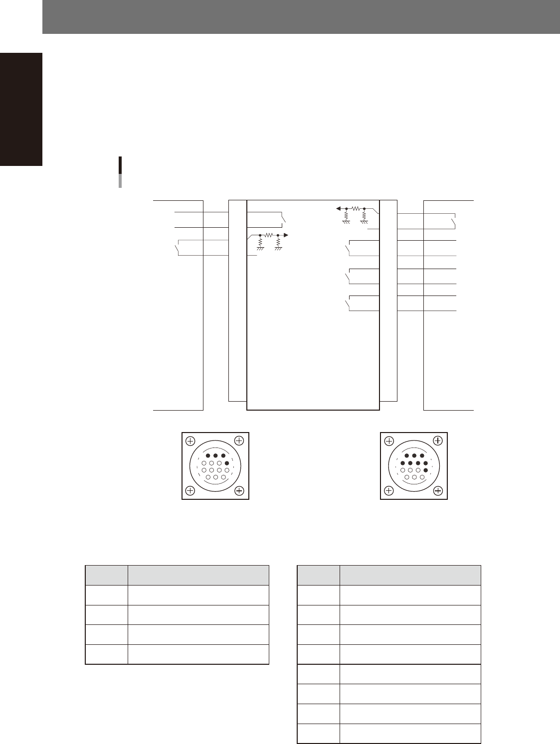
The interface connector labeled "NEXT INTERFACE" connects to the next process machine (downstream
machine), and the interface connector labeled "PREVIOUS INTERFACE" connects to the previous process
machine (upstream machine). Both connectors are AMP 206043-1 (14-pin receptacle).
Each connector is installed inside the left and right cover on the lower rear of the machine. For the dual lane,
the connector is provided at two locations of each lane. The connectors are classified into lane 1 and lane 2.
14
11
12
7
4
8
3
1
7
12
4
8
1
14
11
3
Machine-to-machine connection example
1
2
3
4
5
6
7
8
9
10
11
12
13
14
1
2
3
4
5
6
7
8
9
10
11
12
13
14
Preceding process machine Next process machineThis machine
DC +24V
DC +24V
Relay output
Input
Input
Input
Input
Relay output
PNP input
PNP input
NEXT INTERFACE connector
AMP 206043-1
(14-pin receptacle)
PREVIOUS INTERFACE connector
AMP 206043-1
(14-pin receptacle)
23504-M9-00
n
Board transfer signal specifications
· PREVIOUS INTERFACE · NEXT INTERFACE
Pin No. Signal specifications Pin No. Signal specifications
1 Board transfer permit 1 Board transfer permit
2 Board transfer permit COM 2 Board transfer permit COM
3 Board transfer request 3 Board transfer request
4 Board transfer request COM 4 Board transfer request COM
5 Inspection result OK (pass)
6 Inspection result OK (pass) COM
7 Inspection result NG (fail)
8 Inspection result NG (fail) COM

A-3
Appendix
3. UPS (Uninterruptible Power Supply)
3.1 Safety precaution
3.1.1 Precautions when shipping or exporting the UPS
When shipping the machine equipped with a UPS, always remove the UPS from the machine and carefully
pack it in a separate box.
Take appropriate measures so that the UPS storage temperature does not exceed the rated range (-15 to +50°C).
If the storage temperature exceeds +50°C, the UPS might malfunction or dilute sulfuric acid might leak from
the UPS battery.
When the UPS is left stored for more than three months, the UPS battery may become unusable. Be sure to
recharge the UPS battery once every three months unless the machine has been installed shortly after shipping.
The UPS used at this time for YAMAHA machines does not fall under the Export Trade Control Ordinance.
3.1.2 Disposing of used battery after replacement
This UPS uses a lead battery, so do not discard it as incombustible waste. Dispose of it properly in compliance
with legal regulations in your country. If any point is unclear about the disposal method, please consult our
sales office or representative.
3.1.3 Safety precautions
When using the UPS, take the following precautions to ensure safety. Failure to follow these safety precautions
may result in serious accidents.
n
Do not connect any other than the specified unit to the UPS output receptacle.
Increased load capacity may shorten the UPS backup time or prevent the UPS from providing sufficient backup power if
an overload occurs or cause the YSi-V power to turn off. For details, refer to the instruction manual that comes with the
UPS.
n
Immediately replace the battery when no longer usable.
Dilute sulfuric acid may leak out from the UPS battery if used when worn down, causing smoke or fire.
n
Do not disassemble, repair and modify the UPS except when replacing the battery.
Electrical shock or fire may result.
n
Do not touch the UPS battery if fluid is leaking out of the inside.
Loss of eyesight or burns may result, if battery fluid gets in eyes or comes in contact with skin. Immediately wash
liberally with pure water and consult a physician for proper treatment.
n
If unusual sounds, odor or smoke is coming out from the UPS, or if battery fluid leaks out,
immediately turn off the YSi-V power switch and the UPS power switch.
Continuous operation under such conditions may cause fire. If this happens, immediately turn off the YSi-V power switch
and also all breakers located inside the rear panel of the YSi-V. Then turn off the UPS power switch.
After checking no power is supplied to the YSi-V and UPS, contact our sales office or representative..
n
Securely ground the UPS during recharging.
When recharging a UPS which is being stored, always connect the UPS to the ground pin of the AC input plug.
n
Install the UPS facing correctly in the YSi-V.
Battery fluid may leak out if the UPS is installed facing the wrong way.
n
Do not block the air intake and outlet vents on the UPS.
Blocking the air vents causes the internal temperature to rise excessively, resulting in malfunctions, breakdowns or fire.
n
Do not use the UPS in locations at high temperatures above 40°C.
The UPS battery may wear down quickly or cause fire. This may also cause breakdown or malfunction.