YSi-V_Ope_E - 第40页
Chapter 1 Par t names and functions Contents 1. YSi-V main unit 1-1 2. Conveyor unit 1-4 3. Axis configuration 1-5 4. Option units 1-7 4.1 Marking unit 1-7 4.2 Laser height sensor 1-8 4.3 3D projector 1-9 4.4 4D angular …
iii
Before using the YSi-V
3. Page layout
The description below shows a typical page layout used in this manual.
3-2
3
Daily operation
2. Warm-up operation
After starting the machine, perform warm-up (aging operation) of servo motor axes.
n
NOTE
A warm-up period of 15 minutes is sufficient.
Note that no warm-up operation is necessary if less than 2 hours have elapsed since the last operation.
1
Carry out the pre-operation check before starting the YSi-V.
For pre-operation checks and starting up the machine, see Chapter 2, "Basic operation".
2
Start warm-up operation.
c
CAUTION
Check that there are no boards on the conveyor before beginning warm-up. If push-up pins are used, remove them. If
a problem occurs during warm-up, press the [Stop] button to stop the operation. Then check the cause of the problem
and eliminate it.
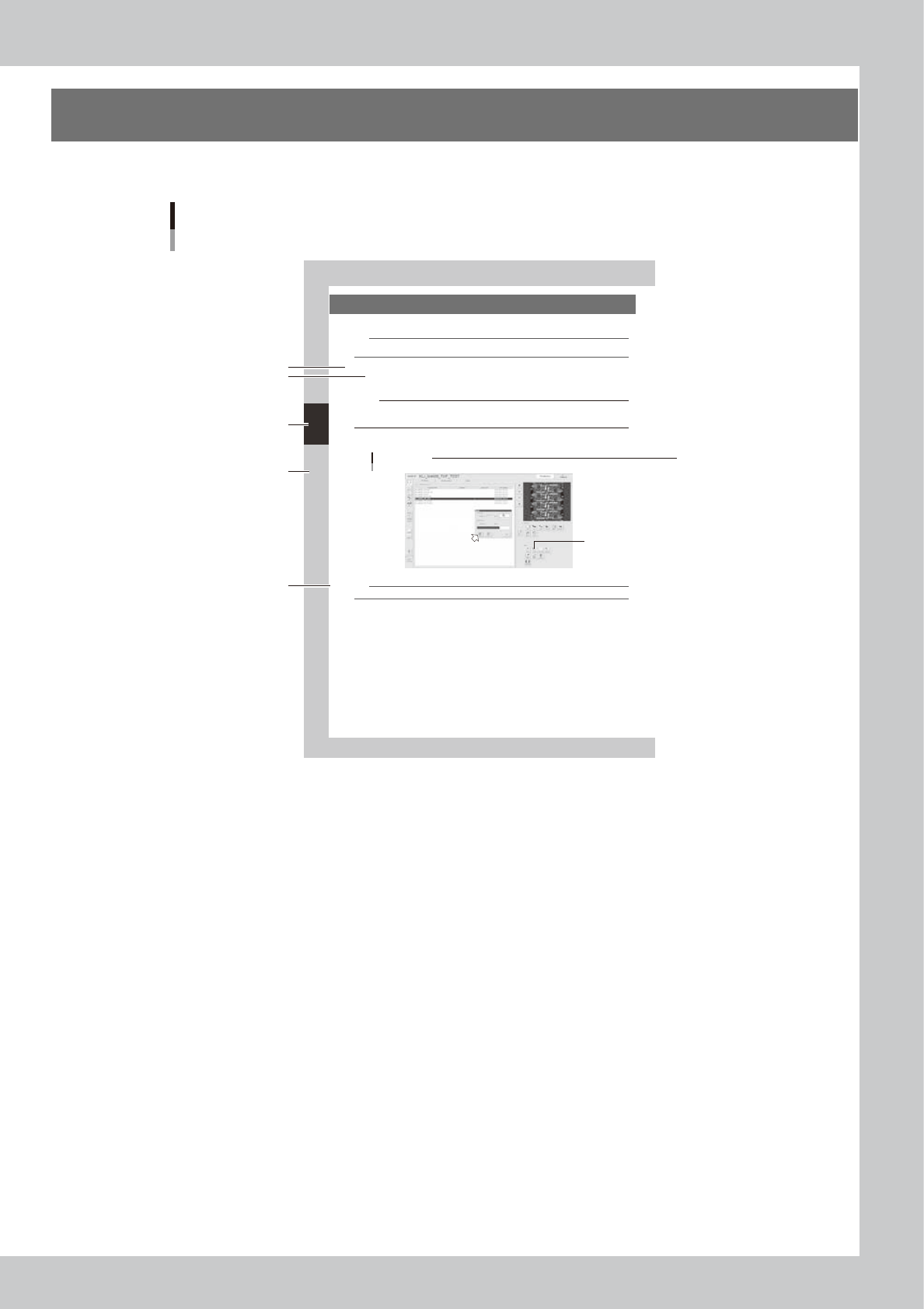
1. Press the [Aging] button to open the war m-up screen.
2. Press the [Start] button to start warm-up operation.
"Setup" screen
Warm-up
2
24300-M9-10
n
NOTE
If you want to specify the warm-up time, press the [Stop after time-over] button and enter the desired warm-up time.
3
End the warm-up operation.
Press the [Stop] button to end the warm-up operation. In most cases, a warm-up period of 15 minutes is
suf ficient.
4
Press the [Close] button to return to the operation screen.
Step
Sub step or
description of step
Typical page layout
Chapter number
Chapter title
Figure, picture
or table caption
Note, Caution
or Warning
23001-M9-00
n
Step
This describes the procedure for each operation.
n
Substep or description of step
This provides detailed information on the steps in each procedure.
n
Figure, picture or table caption
This is the title of the figure, picture or table and appears at the upper left.
n
Note, Caution or Warning
These are explained in detail in "Safety" instructions.

1-1
1
Part names and functions
1. YSi-V main unit
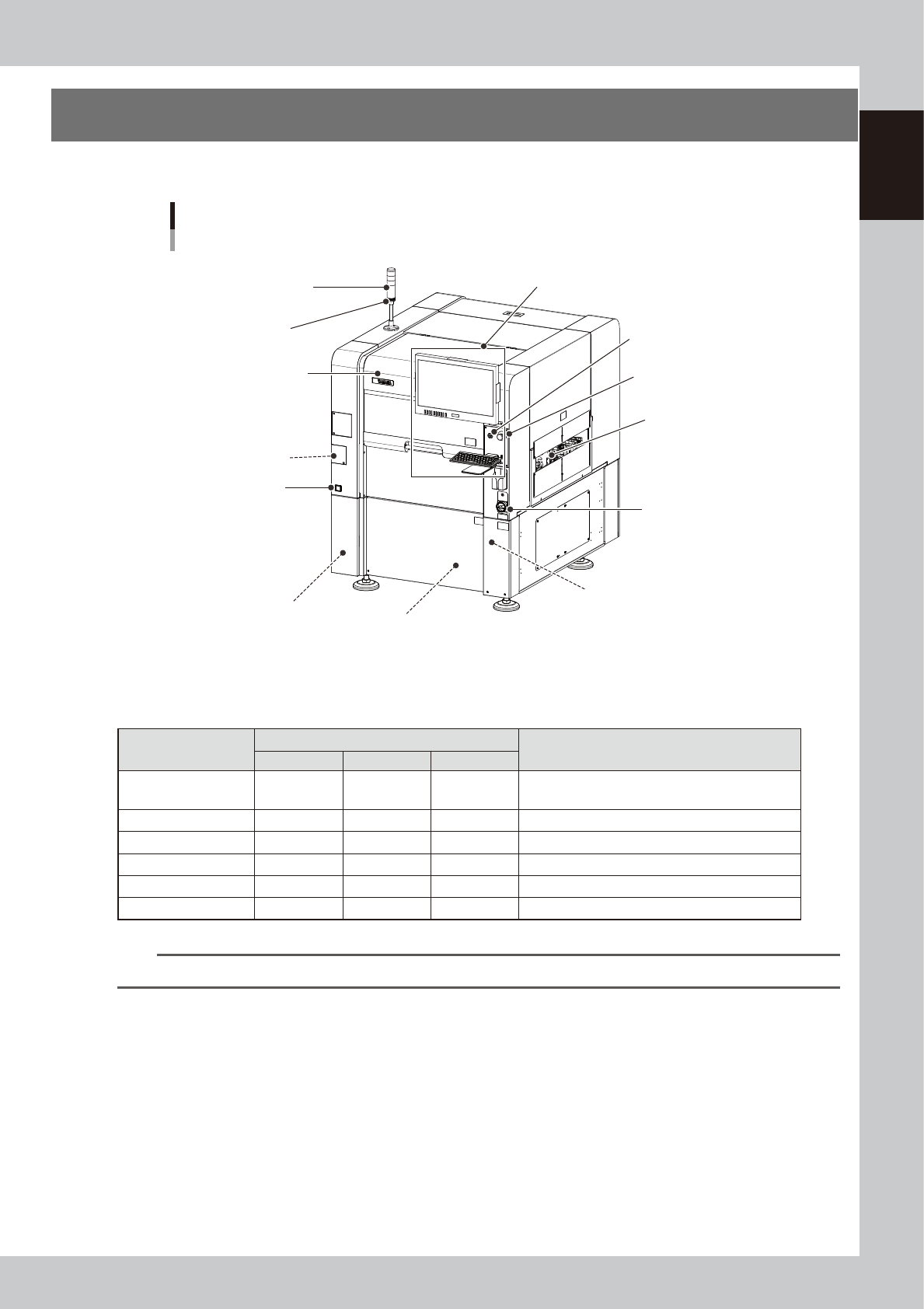
This section describes names and functions of major parts of the YSi-V main unit.
Safety cover
YSi-V main unit
Signal light
(signal tower)
Operation display and data input unit
Main switch
Pressure gauge
Board conveyor entrance/exit
USB port
(behind panel)
Air supply/shutoff switch
(behind panel)
Alarm buzzer
Power connection terminals
(behind panel)
UPS
(Inside panel)
[READY] button
Emergency stop button
23100-M9-00
n
Signal light (signal tower)
Indicates the state of the YSi-V in green, yellow and red or in green, blue and white.
Operation status
Default lighting pattern
Description
Red (White)
Yellow (Blue)
Green
Standby OFF OFF Flashing
Waiting for board to be supplied from the previous
stage.
Auto inspection OFF OFF ON Board has been loaded and is being inspected.
Waiting for judgment OFF ON OFF Waiting the final pass/fail decision input.
Other than AUTO OFF OFF OFF Machine is in a mode other than "auto inspection".
Machine error ON OFF OFF A machine error or emergency stop has occurred.
Emergency stop ON OFF OFF Machine is in emergency stop.
n
NOTE
Signal tower lighting pattern can be customized by machine setting.
n
Alarm buzzer
This buzzer sounds if an error or abnormal operation occurs. (The buzzer volume can be adjusted by turning the buzzer
ring right or left.)
n
Safety cover
Always use the handle when opening or closing this cover.
n
Emergency stop button
Pressing this button triggers emergency stop and turns off the servo power. To release the emergency stop button, turn it
to the right.
n
[READY] button
When emergency stop is canceled, pressing this [READY] button turns on the servo power and the button lights up.