YSi-V_Ope_E - 第42页
1-2 1 Part names and functions n Operation display and data input unit T he keyboard and mouse to be used for YSi-V operation and data input are equipped with the YSi-V as a standard feature. n Board conveyor entrance/ex…
1-1
1
Part names and functions
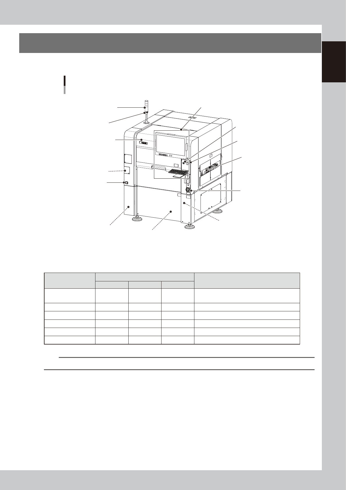
1. YSi-V main unit
This section describes names and functions of major parts of the YSi-V main unit.
Safety cover
YSi-V main unit
Signal light
(signal tower)
Operation display and data input unit
Main switch
Pressure gauge
Board conveyor entrance/exit
USB port
(behind panel)
Air supply/shutoff switch
(behind panel)
Alarm buzzer
Power connection terminals
(behind panel)
UPS
(Inside panel)
[READY] button
Emergency stop button
23100-M9-00
n
Signal light (signal tower)
Indicates the state of the YSi-V in green, yellow and red or in green, blue and white.
Operation status
Default lighting pattern
Description
Red (White)
Yellow (Blue)
Green
Standby OFF OFF Flashing
Waiting for board to be supplied from the previous
stage.
Auto inspection OFF OFF ON Board has been loaded and is being inspected.
Waiting for judgment OFF ON OFF Waiting the final pass/fail decision input.
Other than AUTO OFF OFF OFF Machine is in a mode other than "auto inspection".
Machine error ON OFF OFF A machine error or emergency stop has occurred.
Emergency stop ON OFF OFF Machine is in emergency stop.
n
NOTE
Signal tower lighting pattern can be customized by machine setting.
n
Alarm buzzer
This buzzer sounds if an error or abnormal operation occurs. (The buzzer volume can be adjusted by turning the buzzer
ring right or left.)
n
Safety cover
Always use the handle when opening or closing this cover.
n
Emergency stop button
Pressing this button triggers emergency stop and turns off the servo power. To release the emergency stop button, turn it
to the right.
n
[READY] button
When emergency stop is canceled, pressing this [READY] button turns on the servo power and the button lights up.
1-2
1
Part names and functions
n
Operation display and data input unit
The keyboard and mouse to be used for YSi-V operation and data input are equipped with the YSi-V as a standard
feature.
n
Board conveyor entrance/exit
Board loading/unloading openings that are connected to the upstream and downstream conveyors.
n
Pressure gauge
Shows the supply air pressure (upper display) and pressure-drop detection level (lower display). Use the pressure
regulator knob and the pressure-drop detection level adjust buttons on the pressure gauge to set each pressure value as
follows:
• Supply air pressure (upper display) : 0.40 MPa (0.39 MPa to 0.41 MPa)
• Pressure-drop detection level (lower display) : 0.33 MPa
n
Main switch
Turns on or off the power to the YSi-V. The power is on when turned to the right.
c
CAUTION
Wait about 10 seconds before turning this power switch back on after turning it off.
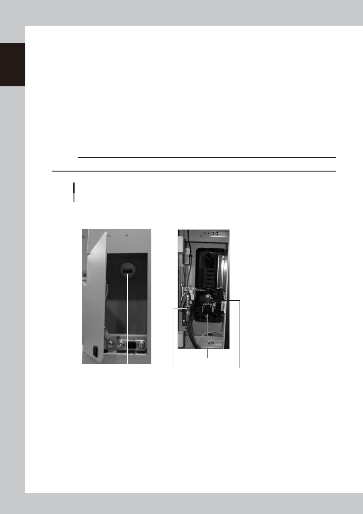
USB port
Air supply/shutoff switch
Pressure regulator
Source air connector
YSi-V main unit
■ Behind center left front panel ■ Behind center left front panel
23111-M9-00
n
USB port
Use this USB port when making a backup of data.
n
Air supply/shutoff switch
Turning this switch to the right shuts off air supply and exhausts air that remains in the air path.
n
Pressure regulator
Adjusts the air pressure supplied to this YSi-V. Turn the knob to adjust the air pressure so that the upper display on the
air pressure gauge indicates 0.40 MPa (0.39 MPa to 0.41 MPa).
n
Source air connector
Prepare an air hose with an inner diameter of at least 8mm having a 30SH socket (Nitto Kohki, or equivalent), and
connect it to this connector. Use dry, clean air passed through an air filter.
1-3
1
Part names and functions
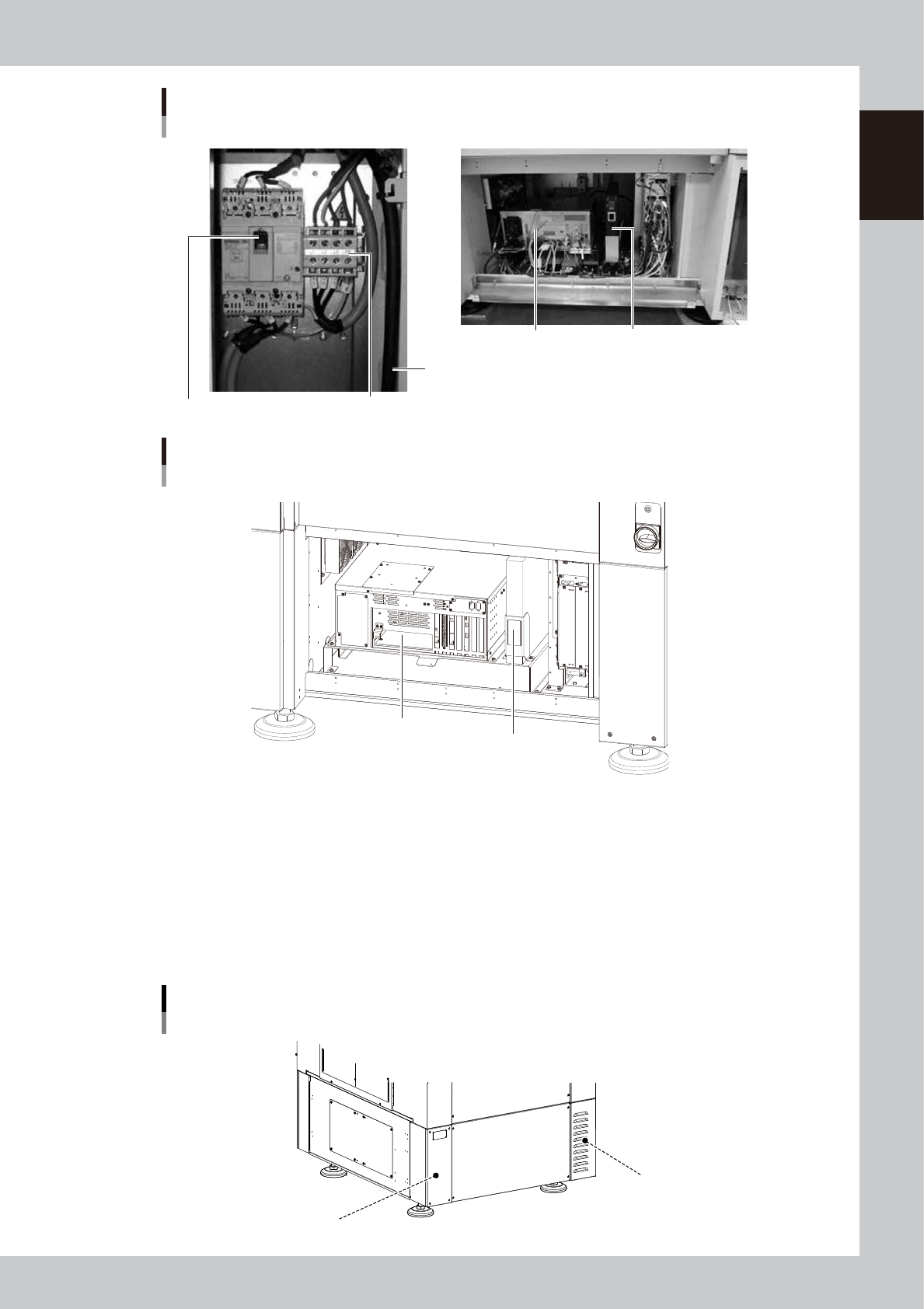
Power connection terminals
Main breaker
Main power cable
YSi-V main unit
■ Inside front lower part of central panel
Controller
UPS (uninterruptible power supply)
■ Behind lower right front panel
23112-L9-10
YSi-V main body
Type HS2 specifications
■ Inside front lower part of central panel
Controller
UPS (Uninterruptible power supply)
23115-L9-00
n
Power connection terminals
Connect a 3-phase AC power cable to this terminal block. ( (For more details, see Appendix "1. Power connection terminals".)
n
UPS (uninterruptible power supply)
The UPS retains (backs up) the power even if abnormal conditions such as power failure or voltage fluctuations occur.
(For more details, see Appendix "3. UPS (Uninterruptible Power Supply)".
n
Machine-to-machine connection connectors (Behind rear panel)
Connector labeled "NEXT INTERFACE" connects to the downstream machine, and the connector labeled "PREVIOUS
INTERFACE" connects to the upstream machine. (For more details, see Appendix "2. Connection between machines".
Machine-to-machine connection connectors
Behind rear panel
NEXT INTERFACE connector
(For connection to downstream machine)
PREVIOUS INTERFACE connector
(For connection to upstream machine)
23108-M9-00