YSi-V_Ope_E - 第44页
1-4 1 Part names and functions 2. Conveyor unit 1. Main stopper 2. Push-up plate 4. Board hold plate 6. Board sensor 3. Push-up pins Conveyor unit YSi-V conveyor (An example of single lane) 5. Board edge clamp unit 23102…
1-3
1
Part names and functions
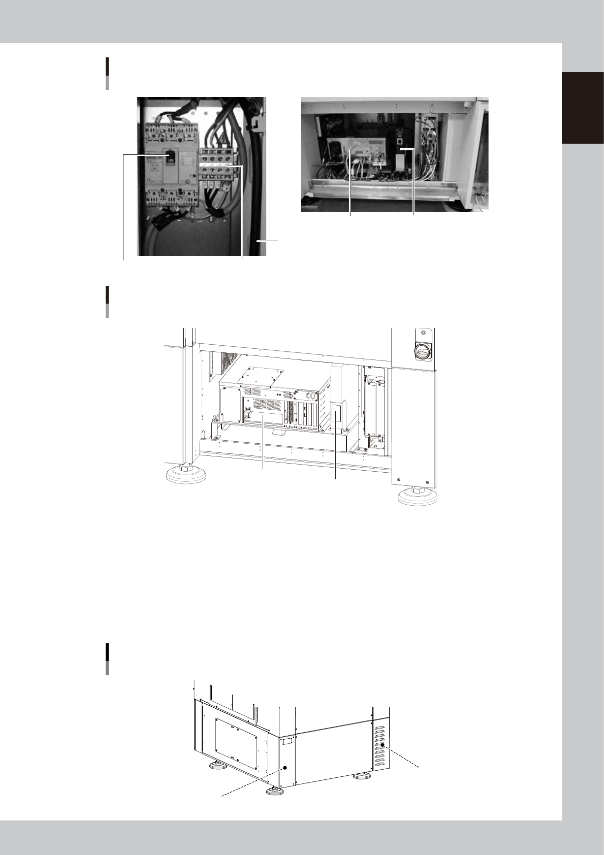
Power connection terminals
Main breaker
Main power cable
YSi-V main unit
■ Inside front lower part of central panel
Controller
UPS (uninterruptible power supply)
■ Behind lower right front panel
23112-L9-10
YSi-V main body
Type HS2 specifications
■ Inside front lower part of central panel
Controller
UPS (Uninterruptible power supply)
23115-L9-00
n
Power connection terminals
Connect a 3-phase AC power cable to this terminal block. ( (For more details, see Appendix "1. Power connection terminals".)
n
UPS (uninterruptible power supply)
The UPS retains (backs up) the power even if abnormal conditions such as power failure or voltage fluctuations occur.
(For more details, see Appendix "3. UPS (Uninterruptible Power Supply)".
n
Machine-to-machine connection connectors (Behind rear panel)
Connector labeled "NEXT INTERFACE" connects to the downstream machine, and the connector labeled "PREVIOUS
INTERFACE" connects to the upstream machine. (For more details, see Appendix "2. Connection between machines".
Machine-to-machine connection connectors
Behind rear panel
NEXT INTERFACE connector
(For connection to downstream machine)
PREVIOUS INTERFACE connector
(For connection to upstream machine)
23108-M9-00
1-4
1
Part names and functions
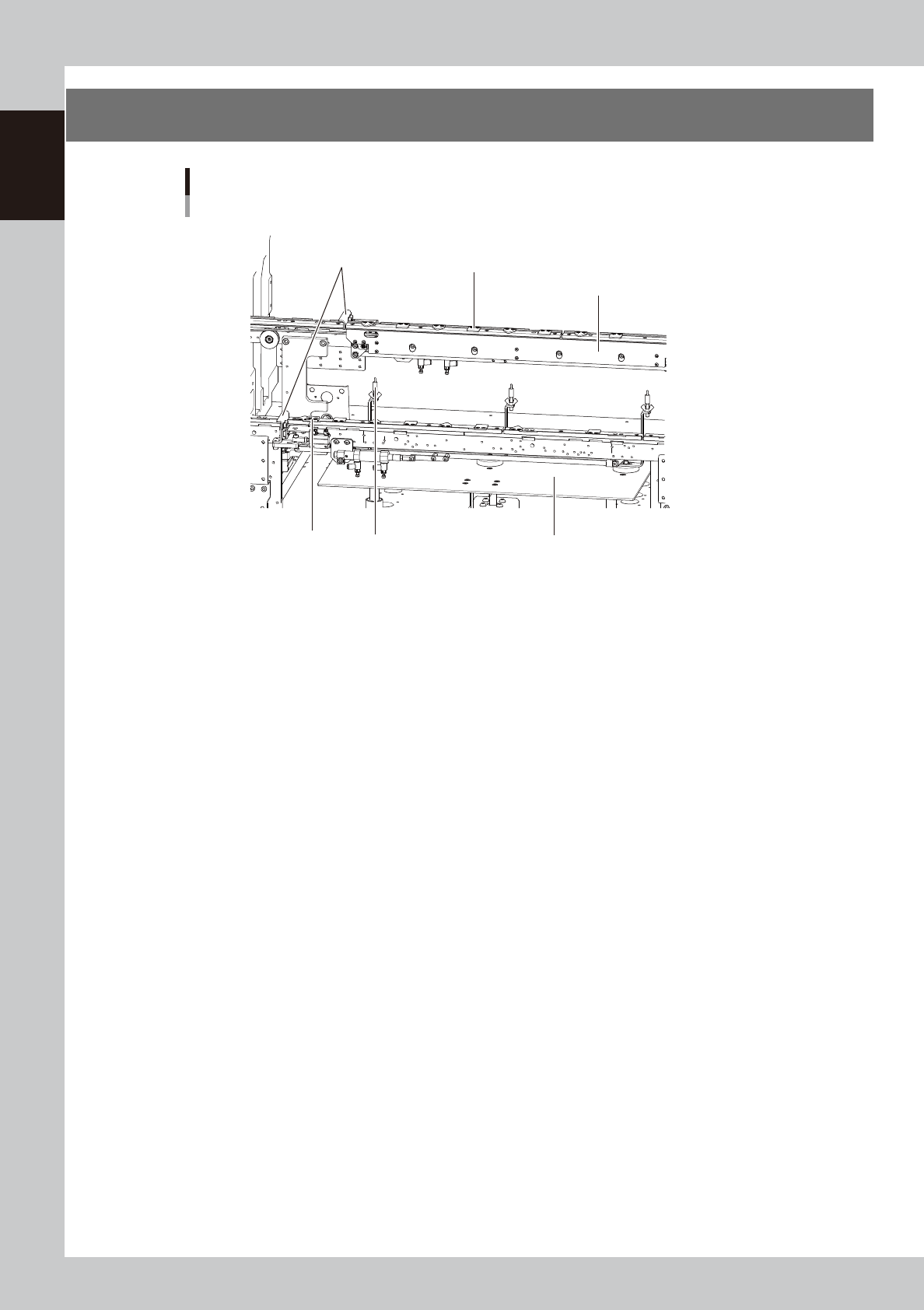
2. Conveyor unit
1. Main stopper
2. Push-up plate
4. Board hold plate
6. Board sensor
3. Push-up pins
Conveyor unit
YSi-V conveyor (An example of single lane)
5. Board edge clamp unit
23102-M9-00
1. Main stopper
When a board is carried in on the conveyor, the main stopper halts travel of the board in the component mounting
position.
2. Push-up plate
The push-up plate clamps the board up against the conveyor rails, with the supporter pins attached by magnet on the
push-up plate.
3. Push-up pins
Install the push-up pins on the push-up plate to support the board from the lower portion. The height of push-up pins can
be adjusted according to the board thickness.
4. Board hold plate (movable)
These plates hold the edges of the board from above when the board is clamped in the mounting position.
5. Board edge clamp unit
This unit clamps the board by pushing its edges up against the board hold plates.
6. Board sensor
Board sensors are arranged at the conveyor entrance and exit, and at the board clamp position, etc.
1-5
1
Part names and functions
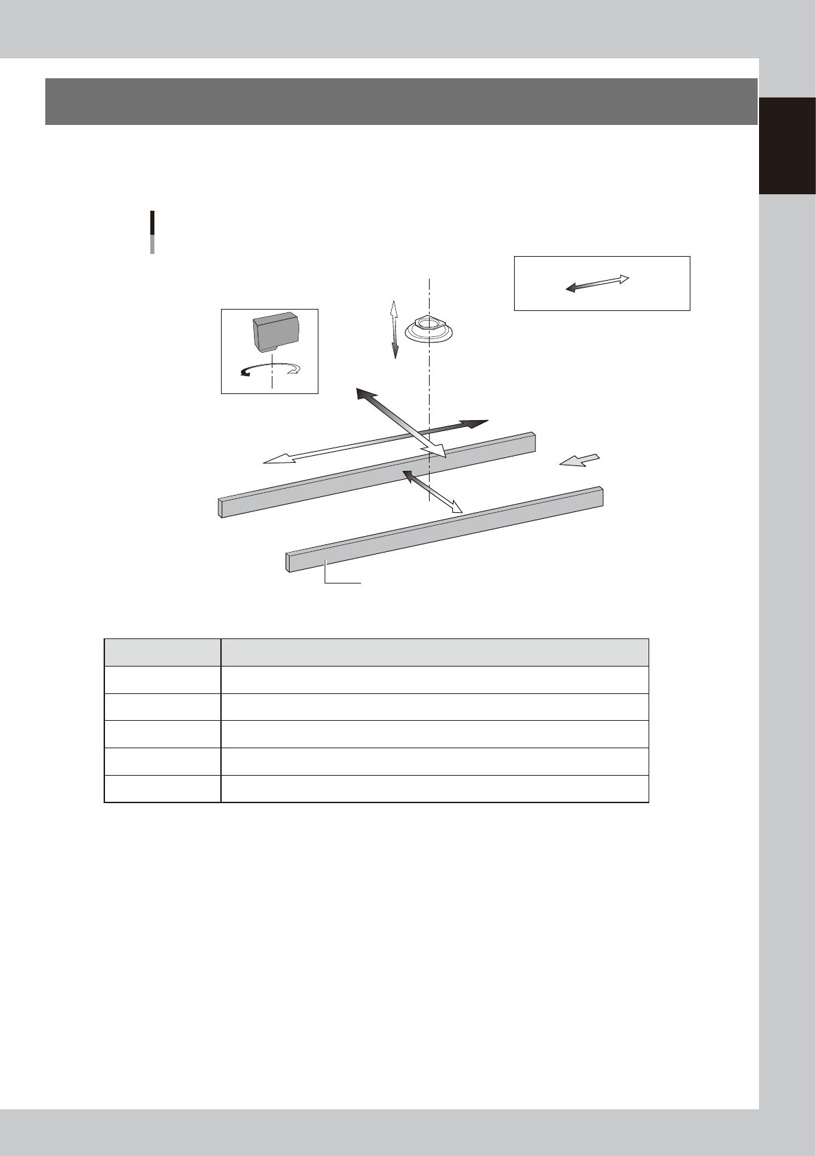
3. Axis configuration
The YSi-V servomotor-controlled axis configuration and movement are shown in the drawing and table below.
n
Single lane
Y-axis
X-axis
Plus direction
Minus direction
Board
Conveyor rail
Axis configuration
Example of single lane, right-to-left flow
W-axis
Laser height sensor : option
CZ-axis
(option)
R-axis
Inspection head
23113-M9-00
n
Function of each axis
Axis Function
X-axis Moves the camera in parallel with the board transport direction of the conveyor.
Y-axis Moves the camera perpendicular to the board transport direction of the conveyor.
CZ-axis * Changes the distance between the inspection head and board.
W-axis Changes the conveyor width.
R-axis Rotates the laser height sensor. (Single lane)
* Option