YSi-V_Ope_E - 第60页
3-4 3 Daily operation 4. Conveyor unit setup When push-up pins are used for board support and the board to be inspected is different from the previous one, the conveyor unit requires setup. The conveyor width is automati…
3-3
3
Daily operation
3. Selecting a board
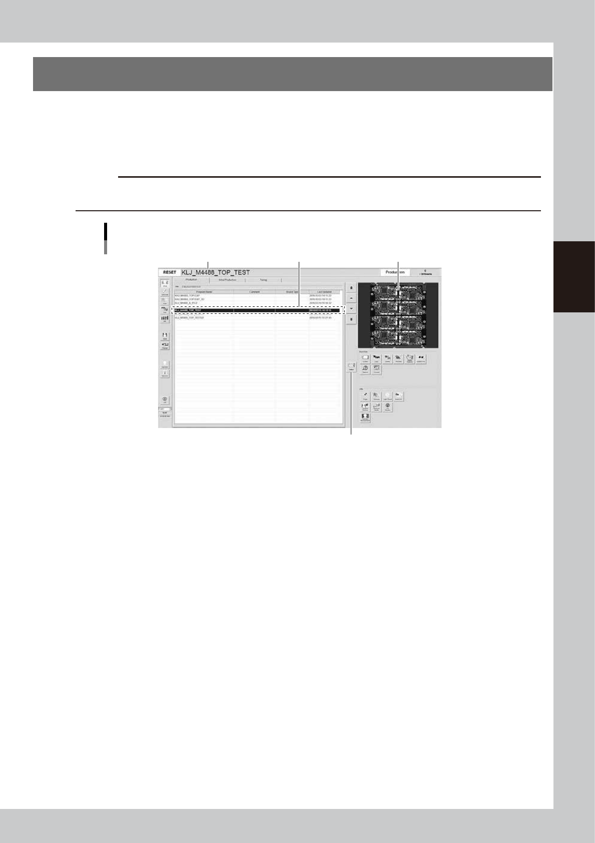
Select the board to be inspected from the list of created programs.
1
In the inspection program list, select the board to be inspected.
Press the [Select] button to read out the board in the list or directly double-click on the corresponding
row in the list to load the inspection program.
c
CAUTION
When the inspection program is loaded, the conveyor width will be automatically adjusted to the board width (board
size Y). Remove the push-up pins before selecting the board.
Selecting board
Select board.Name of inspection program loaded Image of board
[Select] button
24301-M9-10
2
Check the loaded inspection program.
The name of the loaded inspection program appears in the status area. Check that this particular name
agrees with the name of the selected board.
3-4
3
Daily operation
4. Conveyor unit setup
When push-up pins are used for board support and the board to be inspected is different from the previous
one, the conveyor unit requires setup.
The conveyor width is automatically adjusted when loading the inspection program.
Here, the manual explains the procedure for laying out the push-up pins and the method of confirming the
status of supporting the board.
n
NOTE
When using the push-up plate, press the [Inspection Data] button to set the "Use Push Up Unit" item of the [Board] tab
to “Standard Use” or “Fast Use”.
n
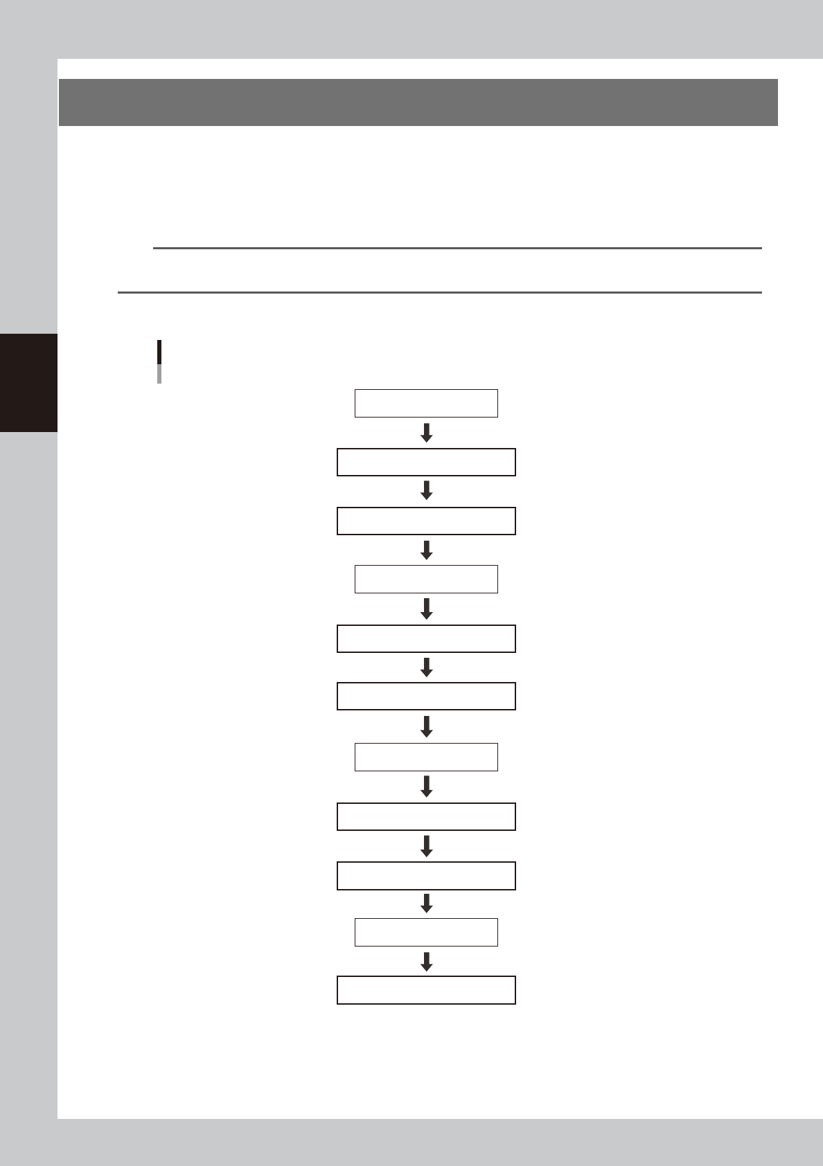
Setup process flow diagram
Load board.
Select board.
Remove push-up pins.
Align push-up pin heights.
Lay out push-up pins.
[Push Up] button OFF
[Push Up] button ON
[Change] button ON
Check that board is secured correctly.
[Change] button OFF
Unload board.
Enter state of emergency stop.
Enter state of emergency stop.
Reset state of emergency stop.
Reset state of emergency stop.
Setup process flow diagram
Push-up pin layout
23301-M9-00
3-5
3
Daily operation
n
Setup procedure
e
1
Press the emergency stop button and then open the safety cover.
2
Remove the push-up pins.
Remove the push-up pins to set up the board to be inspected.
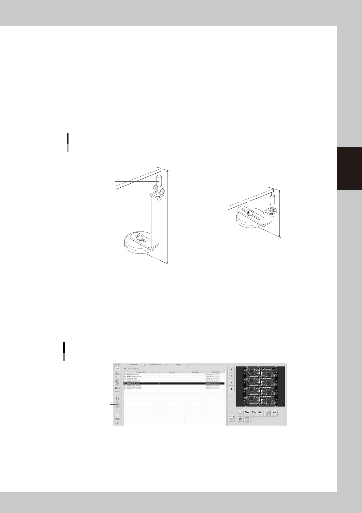
3
Adjust the push-up pin height.
Turn the support pins to adjust the height according to the thickness of the board to be inspected.
The push-up pin height of the single lane may vary from that of the dual lane.
• Support pin height for single lane : 140 mm – board thickness
• Support pin height for dual lane : 76 mm – board thickness
Push-up pin
Height adjustment
76 mm
140 mm
Support pin
Board
Magnet stand
Support pin
■ For single lane
■ For dual lane
Board
Magnet stand
23302-M9-00
4
Close the safety cover and reset the state of emergency stop.
Close the safety cover, cancel the emergency stop state, and press the [READY] button.
5
Select the board.
Select the board to be inspected.
6
Place a board at the inspection position.
Press the [Change] button and then place a board at the entrance of the conveyor.
[Change] button
[Change] button
24302-M9-10
e
7
Open the safety cover.
After making sure the board is clamped, press the emergency stop button and then open the safety
cover.