YSi-V_Ope_E - 第75页
4-11 4 Maintenance 5. Monthly 5.1 Inspecting each axis Inspect the ball screws and the guides on each axis. Check the follo wing points. n NOTE A grease spattering prevention cover is attached along each axis. Remove the…
4-10
4
Maintenance
4. Weekly inspection
4.1 Checking the board sensor condition
This equipment uses transmission type fiber sensors as the board sensors. Periodically check that these sensors
correctly operate even when the conveyor rail width is changed.
1
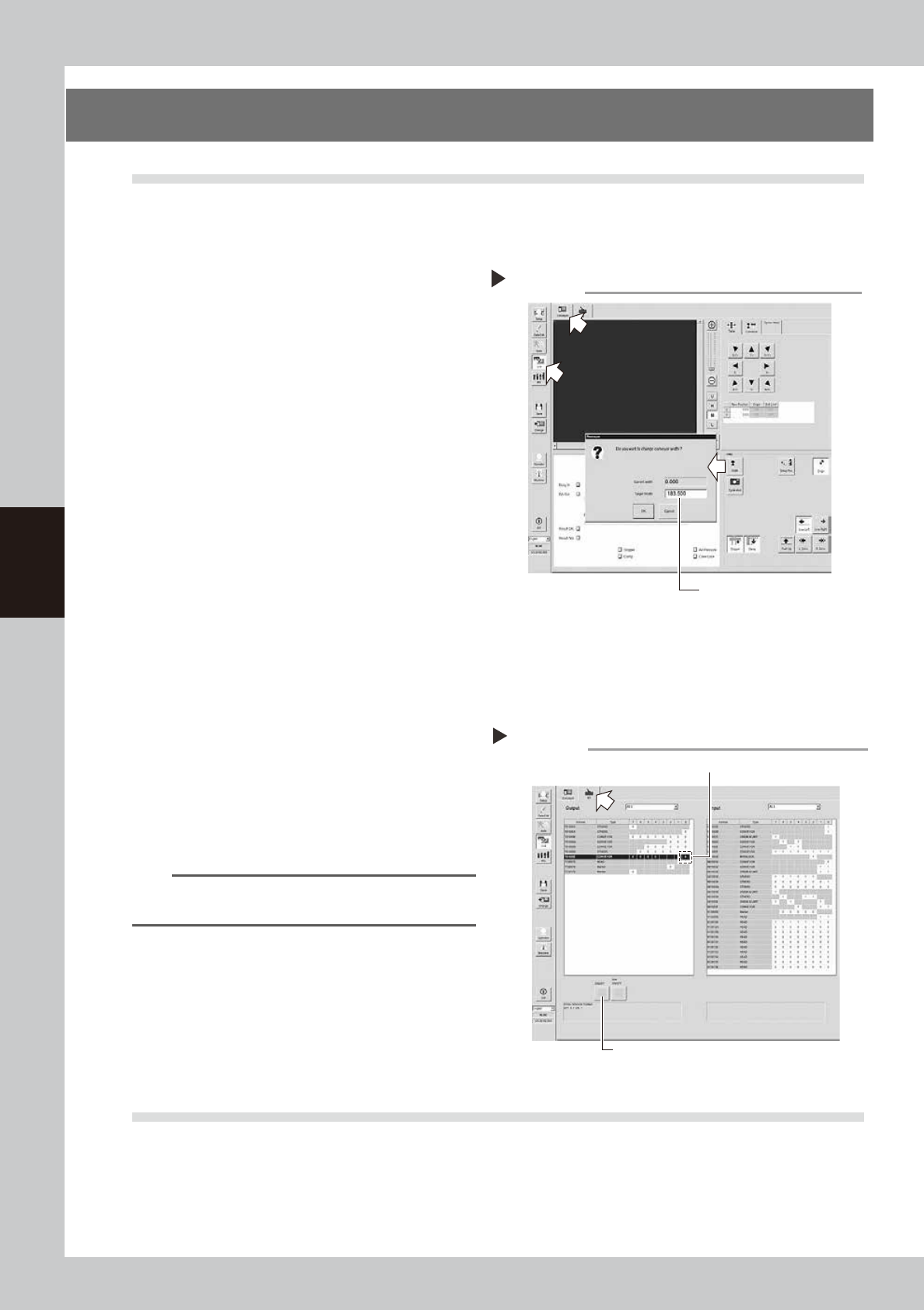
Open the [Unit] – [Conveyor] tab.
2
Press the [Width] button to change
the conveyor width.
1. When the “Conveyor” dialog box
appears, enter the maximum conveyor
width in the "Target Width" box and press
the [OK] button. The conveyor width will
automatically change to the specified
size.
2. Then, enter the minimum conveyor width
(50mm) in the “Target Width” box and
press the [OK] button. The conveyor
width will automatically change to the
specified size.
54400-M9-10
3
Check whether an error has
occurred.
The conveyor sensor is operating properly
unless an error message appears when the
conveyor width is changed. No further
check is necessary.
If an error message appears, follow the steps
below to adjust the sensor.
n
Adjusting the conveyor sensor
If an error occurred when the conveyor width was
changed, perform the auto-tuning of the conveyor
sensor.
1. Open the [Unit] – [I/O] tab.
2. In the Output list, select “CONVEYOR” (T01000E0).
n
NOTE
For the dual lane specifications, (T01000E0) corresponds
to lane 1 while (T01000E2) corresponds to lane 2.
3. Press the [ON/OFF] button to change to 0 (OFF)
→
1 (ON)
→
0 (OFF) and perform the auto-tuning.
4. Press the [Width] button again to change the
conveyor width in the same manner as described in
Step2. When no error message appears, the sensor
operates correctly.
54401-M9-10
4.2 Checking the board clamp condition
Check the following points when a board is clamped on the conveyor.
1. Check that the board is securely clamped and there is no play.
2. Check that there is no clearance between the board hold plate and the board.
3. Check that the board surface is flush with the conveyor rail upper surface.
4. Check that the board clamp unit moves smoothly.
Changing the conveyor width
Enter the conveyor width here.
Step 2
Tuning conveyor sensor
3
2

4-11
4
Maintenance
5. Monthly
5.1 Inspecting each axis
Inspect the ball screws and the guides on each axis.
Check the following points.
n
NOTE
A grease spattering prevention cover is attached along each axis. Remove the cover before inspection and reattach
it in place after inspection.
Checkpoints
1. Any foreign matter or chips adhering to the ball screws and linear guides?
2. Do the ball screws and linear guides have the correct amount of grease?
Check if grease has flowed off or splattered in the air failing to adhere. Also check if grease has discolored or
hardened.
3. Any abnormal sounds from the ball screws?
Press the emergency stop button. Then check for any abnormal sounds while pushing the unit by hand along the X-axis
or Y-axis back and forth.
Countermeasures
1. Ball screws and linear guides may be damaged when chips or debris bite into them. If chips or debris are adhering,
wipe them off along with the grease or remove with tweezers, etc.
2. Apply grease while referring to "Cleaning and greasing the ball screws and linear guides of each axis" described later.
3. Consult your YAMAHA sales office or representative when abnormal sounds occur even after trying the
countermeasures in the above steps 1 and 2.
c
CAUTIN
• When handling grease or lubricant, read and follow the precautions listed in section "3.2.2 Lubricating tools and
grease", in this chapter.
• If abnormal noise is emitted from the ball screw or guide of each axis, then contact our sales representative for
assistance. Disassembly and cleaning of the ball screw or guide by the user will void the warranty.
4-12
4
Maintenance
5.2 Cleaning and greasing the ball screws and linear guides
To clean and grease the ball screws and linear guides of each axis, follow the steps below. See "Chapter 5
Lubrication points" for the modes and points of lubrication.
5.2.1 Cleaning and greasing the X axis ball screws
n
Required tool
• Phillips screwdriver
• Lint-free paper wipe
• Grease gun
• Specified grease (NSL)
• Protective glasses
• Protective gloves
c
CAUTION
Wear protective glasses and gloves when handling grease.
e
1
Press the emergency stop button.
The YSi-V must be in emergency stop to
ensure safety during work.
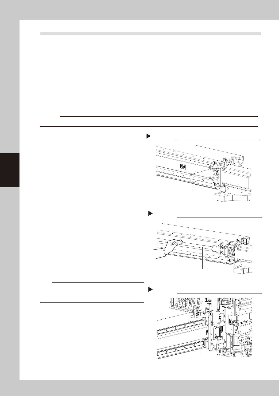
2
Remove the grease spattering
prevention cover.
1. Use a Phillips screwdriver to remove the
left side of the grease spattering
prevention cover.
2. Move the head all the way to the left
side and remove the screws securing the
right side of the grease spattering
prevention cover.
3. Remove the grease spattering prevention
cover by pulling it to the right.
53401-M9-00
3
Clean the ball screws.
1. Wipe away the old grease and dirt from
the entire ball screw with a lint-free cloth
or paper towel (for clean room).
2. Move the head to the opposite end of
each axis and wipe the ball screw clean.
53402-M9-00
n
NOTE
Wipe away the old grease and dirt in the lead groove
of the ball screw. Also check that no debris or residue
remains in the lead groove.
4
Apply grease to the ball screws.
Use the grease gun to supply the specified
grease (NSL) to the grease nipples.
Then move the head back and forth by
hand along each axis and wipe away
excess grease.
53403-M9-00
5
Reattach the covers.
Reattach the grease spattering prevention
covers in the reverse order of the removal
procedures.
Removing the X-axis grease spattering prevention cover
Cover mounting screw
Step 2
Cleaning the X-axis ball screws
Step 3
X-axis ball screws
Cleaning cloth
Greasing the X-axis ball screws
Step 4
Grease nipple for
X-axis ball screws